Enhanced Dynamic Cross Layer Mechanism for real time HEVC Streaming over Vehicular Ad-hoc Networks (VANETs)

Adv. Sci. Technol. Eng. Syst. J. 7(2), 18–24 (2022);
 DOI: 10.25046/aj070202
Various applications have helped make vehicular Ad-hoc network communication a reality. Real-time applications, for example, need broadcasting in high video quality with minimal latency. The new High-Efficiency Video Coding (HEVC) has shown great promise for real-time video transmission through Vehicle Ad-hoc Networks due to its high compression level. These networks, on the other hand, have highly changeable channel quality metrics and limited capacity, making it challenging to maintain good video quality. HEVC real-time video streaming on VANET may now benefit from an end-to-end dynamic adaptive cross-layer method. According to the video coding process’s time prediction structure, frame size, and network density, each video packet should be assigned to a suitable Access Category (AC) queue on the Medium Access Control layer (MAC). The results we’ve gotten demonstrate that the new method suggested delivers considerable improvements in video quality at end-to-end latency and reception in comparison to the Enhanced Distributed Channel Access (EDCA) specified in the 802.11p standard for several targeted situations. Quality of Experience (QoE) and Quality of Service (QoS) assessments have been used to verify our proposed strategy.
1. Introduction
As the idea of a city linked to the internet becomes closer to reality, the effect of the internet on our lives grows. Nowadays this may be realized with the appropriate use of traffic safety and entertainment applications in the form of vehicular networks. Inter-vehicle or infrastructure communication network may be used for a variety of purposes, but one of the most intriguing is video streaming. For this reason, it isn’t easy to broadcast video through automobile networks. The transmission of video content over vehicle networks would represent a big step forward [1]; Overtaking maneuvers, parking assistance, video communication, video surveillance, and public transport assistance, and for entertainment, the possibility to use visual information data [2], [3]. However, compressed videos are susceptible to noise and channel loss. Although virtual networks are plagued by harsh transmission circumstances and packet loss rates (PLR) that do not ensure the quality of service, there are other issues.
Several technological solutions have been suggested to improve multimedia transmissions over vehicle networks [4]. Particularly, the IEEE 802.11p standard, which has been solely dedicated to vehicle networks, At the MAC layer, the standard handles QoS differences by offering distinct service classes [5]. In contrast, the HEVC/H265 standard has recently been developed and put at the disposal of scientists; this new standard outperforms its predecessor (H264/AVC) coding efficiency-wise by about 50% [6]. Due to the requirements of video transmission, inter-vehicle applications using video, like traffic optimization and monitoring, ensuring low delay has become essential [7], [8].
It is even more important in remote vehicle control applications and driver assistance systems [9], given the recent interest in autonomous vehicles. Therefore, a communication system ought to ensure both low latency and high reliability [10].
In a vehicle environment, the received signal intensity can vary considerably because of several factors; fading, shading, multipath, and Doppler effect are the main ones. Therefore, VANETs are networks with difficult channel conditions resulting in a degradation of the output of the link, which results in poor quality of the video. To address this, many studies have evaluated video quality as a network load function [11] or the video source encoder [12]. Authors in [13] suggested real-time performance assessment of video transmission in-vehicle environments. Specifically, their research looked at vehicle density and distance effects on HEVC-encoded video sequences in the road and urban environments. As assessment measures, the peak signal to noise ratio (PSNR) and the packet delivery ratio (PDR) were calculated. A change to the Real-Time Transport Protocol (RTP) was developed by authors in [1] to make the H.264 encoded video transmission more efficient to enhance the transfer of information. The implementation of video transmission in VANET was also studied. Using a retransmission technique in [14] devised an error recovery mechanism. MPEG4 part 2 video is encoded with uneven protection of video images, according to the standard. Regarding video streaming through VANET networks, researchers in [15] employed network coding and blanking coding.
Improvements were also made to EDCA for video transmission on the IEEE 802.11e standard. Background traffic (BK), best effort (BE), which EDCA makes accessible in accordance with the meaning of video coding, were initially proposed by authors in [14] and have since been widely used. A mapping algorithm based on the IEEE 802.11e EDCA traffic standard was suggested by the authors to increase H.264 video transmission over an IEEE 802.11e network. But since this used mapping algorithm is static, it does not reflect the network state. IEEE 802.11e wireless networks might benefit from a dynamic cross-layer mapping technique developed in [16], which they believe would be effective. Authors in [17] created a cross-layer framework enabling H.264/AVC video streaming through IEEE 802.11e wireless networks, which was published in IEEE Communications Magazine. The suggested technique provides for more effective use of the radio source by assessing the access time for each AC and selecting the AC with the shortest access time. However, the work stated for cross-layer approaches is particular to the IEEE 802.11e standard and is grounded on the previous standards for video encoding; the video encoder’s ability to cause modifications in the temporal standards prediction framework has not been taken into account. On top of that, they do not take into consideration the issue of latency for a low-delay transmission. Researchers in [18] developed a framework of delay rate distortion in wireless video communication employing H. 264’s LD mode, which is constructed from predicted and intra frames, called P and I frames respectively.A real-time H.265/HEVC stream transmission technique was suggested by authors in [19]. The optimal time prediction is chosen by algorithms to be used by considering the decoding and encoding times of the Network QoS and HEVCs.
To optimize HEVC video streaming on VANETs, we have created a dynamic cross-layer technique. We propose a mapping mechanism that is devoted to the IEEE 802.11p standard to increase the efficiency of video streaming in Vehicular Adhoc networks with fluctuating network topology. HEVC’s new temporal prediction structures allow us to make use of our approach. The IEEE 802.11p and HEVC standards have influenced the re-design of the method initially described in [20] and [16]. Both the relevance of the channel state and the video frame, controlled by the queueing system of the MAC layer, are taken into account by the suggested approach. Taking into consideration the video’s temporal prediction structure, frame significance, and current traffic load, each packet of the transmitted video is assigned to the most suitable AC queue on the MAC layer.
Section 2 highlights our proposed solution in detail. In section 3, we will focus on our work approach and simulation. Section 4 contains the simulation results that demonstrated the proposed solution’s effectiveness, providing 18% average received packet gain in comparison to the IEEE 802.11p EDCA mechanism. Conclusion is described in the last section (Section 5).
2. Description of the proposed solution
For the purpose of achieving considerable performance advantages, cross-layer design refers to a method that takes advantage of the reliance across protocol levels. Depending on how information is shared across layers, several different design types may be identified. Authors in [21] narrowed the range of feasible designs down to four distinct methods. Using the first way, new interfaces are created. The second involves merging nearby layers, the third consists of the designed integrating without new interfaces, and the last approach involves the vertical calibration across the layers.
The proposed cross-layer architecture takes use of information about video packets’ relevance obtained from the application layer to regulate this on the decision-making process at the MAC layer when video packets are considered necessary. The technologies that were used in this project will be discussed in further detail later in this section. We will begin by discussing the properties of IEEE 802.11p, which are unique to vehicle networks, and then move on to more general considerations. As a second step, we will offer a high-level overview of H.265/HEVC encoding before presenting our suggested cross-layer architecture.
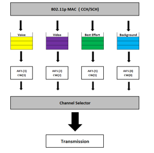 Figure 1: The different access categories in the IEEE802.11p MAC architecture.
2.1. The IEEE 802.11p standard
The IEEE 802.11p standard is an accepted addition to the IEEE 802.11 standard for providing wireless connectivity in a vehicle context. It was approved by the IEEE in 2009. (WAVE). The standard’s PHY layer is based on the DSRC (dedicated short-range communication) standard. It operates in the 5.850-5.925 GHz frequency band, with a IEEE 802.11a modified version serving as the physical layer. According to [22], DSRC is regarded to be capable of providing communication for both vehicular to infrastructure (V2I) and vehicle to vehicular (V2V) situations. The European Standard Telecommunications Institute (ETSI) describes ITS-G5 as the comparable standard in Europe to the IEEE 802. p standard, which is devoted to the United States [23]. There are some discrepancies between the two standards at the higher levels, although they are minor. Despite this, it operates in the same frequency range as the DSRC [24]. In Japan, the equivalent of the DSRC is utilized in the 5.8 GHz frequency band, which is composed of six service channels (SCH) and one control channel. It also uses a 3 Mbps preamble supports data speeds of 3, 6, 9, 12, 18, 24, and 27 megabits per second. Orthogonal Frequency Division Multiplexing (OFDM) is the modulation technique used (OFDM).
The IEEE 802.11p standard’s medium access control layer protocol employs CSMA/CA (Carrier Sense Multiple Access with Collision Avoidance) as the principal medium access mechanism for link sharing and EDCA for packet transport [25]. The EDCA protocol, in conjunction with flow prioritizing in accordance with QoS criteria [26], facilitates service hierarchization. The IEEE.802.11e standard was first introduced, and it has since undergone several revisions [27][20]. Actually, EDCA is an advance over the distributed channel access (DCA) technique to provide the necessary quality of service (QoS). A single queue for holding data frames is replaced by four queues, each indicating a distinct degree of priority or access category, referred to as ACs in this document. Every one of these acs is allocated to a certain kind of traffic, as depicted in Fig.1, with the background (BK), video (VI), voice (VO), and best effort (BE) being examples.
The higher the transmission priority, the greater the likelihood of successful transmission. Priority is allocated to each traffic stream by the relevance of that traffic stream. Priority has been given to VoIP traffic, which was followed by video, background traffic, and best-effort, all of which had lower priority.
The waiting time TAIFS (Time Arbitration Inter-Frame Space), which represents the time required for each AC to access the media, is used to determine the priority of each AC. It enables varying prioritizing of frames based on the kind of traffic being sent. Time between frames may be reduced by using a short TAIFS, for example, and the time required to connect to the medium. TAIFS value is given by [27]:
T AI FS [AC] = AI FSN[AC] ∗ aSlotTime + S I FS (1)
The AIFSN [AC] (Arbitration Inter-Frame Space Number) is the constant that corresponds to each AC, which is the AC of each traffic type. There are specified consistent intervals for the Short Inter-Frame Space and aSlotTime in the standard, 32 and 13 second time frames. The contention windows are another distinction between the ACs (CW).
Internal queue clashes are possible since EDCA has four queues. The process mentioned before aids in the resolution of these issues. Figure 2 displays an illustration of competing for access to the media and the TAIFS prioritizing system. As can be seen, a best effort frame and a voice frame are in a heated competition for access to the media. In order to reach the medium, the AC voice’s reduced wait time allows it to forego its best effort. Each AC’s value is listed in Table 1[27]. Distinct ACs have different CW and AIFSN values set in the CCH and SCH. According to smaller TAIFS, we conclude that video AC has a higher priority than the BK and BE.
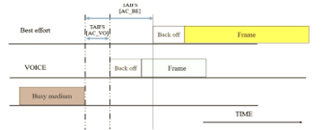 Figure 2: the medium access in EDCA IEEE802.11p.
2.2. Encoding modes for H265/HEVC
HEVC, like its predecessor H264/AVC, follows a hybrid video coding scheme. Both video coding standards have a two-layered high-level design consisting of a network abstraction layer (NAL) and video coding layer (VCL). The VCL includes all low-level signal processing, including inter-and intra-picture prediction, block partitioning, transform coding, in-loop filtering, and entropy coding. At the top-level, an HEVC sequence consists in a series of network adaptation layer (NAL) Units or NALUs. These NALUs encapsulate compressed payload data and include parameter sets containing key parameters used by the decoder to correctly decode the video data slices, which are coded video frames or parts of video frames [16].
It is conceivable to envision video transmission, especially in real-time, in networks with little capacity or a high packet loss rate because of the general benefit of HEVC. As it is considered a hostile network, strong level of resistance and compression is required for transmission of video in the VANET. This is because transmission of video in the VANET is considered to be pretty hostile. HEVC has been shown by researchers in [19] to exceed its predecessors significantly when it comes to decreasing temporal error propagation in changeable wireless video environments. Their study compared the HEVC encoding pattern with an LD configuration to the traditional MPEG-4 part 2, H.264/AVC, and H.263 coding standards under various packet loss rates.
Predictions from future pictures are prohibited to ensure low latency operations at both the decoder and encoder. While the short-latency restriction may be met by employing P-images solely, the directional motion compression efficiency estimate is lost due to this practice. Generalized P-B (GPB) pictures are introduced in HEVC to reduce the time to process a B- picture while still delivering excellent coding performance [25]. A GPB is a bi-predictive frame that employs just previous pictures for inter-prediction in GPBs.
Error-resilience, processing time, computational complexity, codec efficiency, and approaches are all considered while configuring HEVC for a specific application. The two most common encoding setups are:
- the “high efficiency” approach that provides highly efficient codingwith a significant computational cost,
- Excellent efficiency with little coder complexity in the “low complexity” mode.
2.3. Proposed cross-layer approach description
Our multilayer system is described in this section. Video transmission at the MAC layer of the IEEE 802.11p standard is limited to the use of the specialized video AC. The other two lower priority ACs may be used to reduce network congestion and the loss of video packets due to video packet overflow.
When it comes to our system’s current development, we are still working on the low latency element. To do this, we’re looking at two low-complexity video transmission techniques:
- Static inter-layer mapping algorithm that is centered on hierarchical HEVC (Figure 3)
- Adaptive inter-layer mapping algorithm that is developed based on hierarchical HEVC (Figure 4)
The Cross-layer system also uses the HEVC hierarchy to map video packets at the IEEE 802.11p standard MAC layer. It is demonstrated that the three levels of stratification in the two suggested multilayer mapping methods are based on the video structure:
For the low delay configuration
- Layer-1: includes level 0 images and level I images
- Layer-2: includes level 1 executives.
- Layer-3: includes level 2 executives.
For the random-access configuration:
- Layer-1: comprises level 1 and level 0 images and I images.
- Layer-2: comprises level 2 as well as level 3 frames.
- Layer-3: comprises level 4 executives.
The choice of the distribution of the frames was established according to the importance, and the size of the frames compressed data. No categorization has been kept for the All Intra configuration.
- Static mapping algorithm
According to the categorization system used, which changes based on the video structure, the pictures associated with layer-1 are the essential images. This is due to the fact that layer-1 pictures have a significant effect and, in some ways, influence everything else in GoP. In this sense, any loss or deterioration that may occur due to their actions will impact the whole GoP. Additionally, it’s worth noticing that the Layer 1 photos include additional information. We recommend creating a static technique for each video structure based on this information. It is always assigned the highest priority for layer 1 frames to utilize alternating current, whereas layer 2 frames are always assigned the lowest priority. It’s a video that’s been made by AC. Route the second most critical Layer 2 frames to the second available queue, which is likely to have the best AC effort available. In this section, we will, however, stratify the video using the method proposed in [20]. When using the static method, we’ll put video packets corresponding to layer 3 in the final queue (BAC).
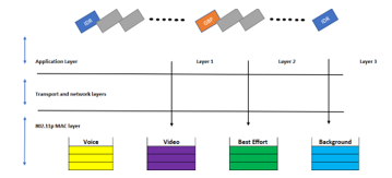 Figure 3 Illustration of the static cross-layer algorithm.
- Adaptative mapping algorithm
Video packets are assigned the most suitable AC currents based on the suggested adaptive mapping method at the MAC layer of the network. Network traffic load, the relevance of each frame, and temporal prediction structure are all considered. As the last step, we must assign each picture type a separate mappings probability to lower priority ACs, denoted as P Layer. The probability is a function of the frame size meaning:
0 ≤P_Layer-1≤P_Layer-2≤P_Layer-3≤1.ù
Alternatively, as previously stated, the channel’s condition affects the mapping. AC queues are a good indicator of network traffic congestion. To avoid overcrowding, it is essential to keep the MAC queue buffer as empty as possible. Random Early Detection (RED) is the philosophy behind the two thresholds that we’ve implemented to manage and minimize network congestion. According to [20], the adaptive mapping method is based on the following formula:
Pnew = PLayer ×
Qlen (AC [VI]) is the real length of the video queue, and qthlow and qthhigh, which are arbitrarily set thresholds, explicitly state the process and the degree of mapping of ACs of lower priority.
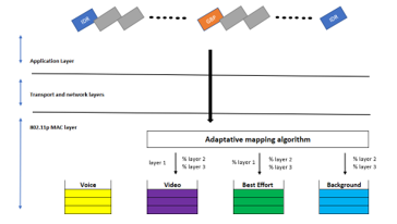 Figure 4 Illustration of the Adaptative mapping algorithm.
3. Framework and Simulation set-up
Integrating a map into a network simulator has been and will always remain a challenging task for researchers. OpenStreetMap was created by academics to tackle this problem and be used in traffic simulations. It is a free customizable map of the globe, has an incredible quantity of data, as well as a high degree of precision. However, since the data is frequently incomplete for traffic simulations, Map acquisition should always be the initial phase; followed by filling the missing sections and enhancing the data before turning it into an OSM file that the SUMO traffic simulator can use.
Figure 5 illustrates the four essential phases of our working method. The following section will discuss each stage in detail.
It is necessary to first download and install MPEG, which is an accepted practice for video streaming over the internet. For this simulation we have used a CIF (H.261) video file format with a 352 x 288. before a CIF file can be used for simulation, a video trace file is generated by running the mp4trace utility on the original MPEG4 movie. If the picture has been segmented, the video trace file provides information on the segments’ number, kind, and size. The mp4trace tool requires the port number and target URL since the Evalvid utility was initially developed to analyze real video transmissions.
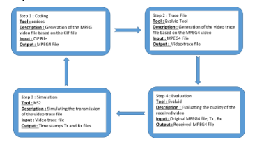 Figure 5 work approach
4. Simulation results
Different routing protocols will be tested in this simulation to see how they work when running in a high-density traffic environment. After 200 milliseconds of simulation, there will be ten to 60 cars, and on each simulation ten vehicles will be added to the total. For the simulation and as mentioned below, UDP was used as a transport layer protocol, and CBR as the application layer protocol.
Table 1: Simulation parameters of routing protocols perpormance evalution
| Parameters | |
| Simulator | NS-2.35 |
| Protocols | AODV, DSDV, DSR, OLSR |
| Simulation duration | 200s |
| Simulation area | 3511m*3009m |
| Number of vehicles | 10,20,30,40,50,60 |
| MAC layer protocol | IEEE 802.11 |
| Application layer protocol | UDP |
| Paquets size | CBR |
And Casablanca’s Anfa area was chosen for our simulation Figure 6.
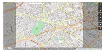 Figure 6 Anfa District Casablanca “OpenStreetMap”
In comparison to Destination Sequenced Distance Vector (DSDV) and Optimized Link State routing protocols (OLSR), Dynamic Source Routing (DSR) and On-demand Distance Vector routing protocols (AODV) have performed better, which is reasonable considering that proactive protocols must sustain a forwarding table for every node in the network. Through the VANETs high mobility, a large number of updates to the routing table must be made momentarily, resulting in bandwidth wastage.
Since it was important to see how well PSNR performed when streaming low-brightness videos, in the second phase of the simulation, we chose to proceed with the AODV protocol as it was the most efficient in terms of throughput, jitter, and packet delivery.
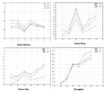 Figure 7 throughput, packet delay, packet delivery, and jitter, and for various network densities (5, 10,20,30,40, 50, 60)
Since it was important to see how well PSNR performed when streaming low-brightness videos, in the second phase of the simulation, we chose to proceed with the AODV protocol as it was the most efficient in terms of throughput, jitter, and packet delivery.
The other parameters are mentioned below:
Table 2 Simulation parameters of PSNR perpormance evalution
| Parameters | |
| MAC layer protocol | 802.11 |
| Routing protocol | AODV |
| Number of vehicules | 4, 9, 25, 64 |
| Image Resolution | 352 * 288 |
| Video file frame size | 30 fps |
“Highway CIF” is the video we utilized for our scenario. When the network sparsity is adjusted to D = 100 m and its density increases, the PSNR performance of the AOADV protocol is shown in Figure 8. To get a better picture of the data, we utilized 100 frames to smooth it down a little.
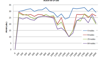 Figure 8 PSNR Performance of AODV for various network densities (4, 9, 25, 64)
At various densities of networks, the brightness of video pictures has an impact on maintaining the PSNR variation model. All frames in this movie have the similar brightness since we send the same video file over many topologies. As shown in Figure 8, this was confirmed by looking at the two significant decreases in PSNR performance. The first happened at a frame rate of around F = 500, or about 19 seconds into the movie viewing. As shown in Figure 9, the brightness reduced during this time due to the emergence of a black automobile in excess. During video playing times of T = 43 and T = 46, the second big reduction in PSNR occurred. In the video, a black bridge initially emerges. After that, the automobile passes over its shadow, as seen in Figure 6. PSNR falls in both circumstances because as a frame’s brightness content drops, noise energy outweighs maximum signal energy, so lower PSNR may be attributed to this fact.
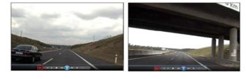 Figure 9 screenshot of the video at T=21s and T=41s
Figure 8 shows that the performance of PSNR of the AODV decreases with the increase in network density. When the network grows from N = 4 to N = 9, the PSNR drops by around 5 dB between Frame = 650 and Frame = 500. However, as the number of nodes in the network changes from N = 25 to N = 64, this attenuation is less relevant. Data must be routed through intermediary nodes when the network density rises to N = 9, 25, or 64 nodes. In this scenario, the PSNR suffers greatly because of the many jumps.
To conclude our simulations, we performed several tests to show the suggested mechanism’s efficacy. Fig.10 illustrates the benefit of the adaptive method. The PSNR curves show how the two mapping techniques change over time. In terms of PSNR, the adaptive technique (red) is superior in performance. In certain peaks, the static approach yields strong PSNR values, indicating good receipt of IDR pictures. This, However, doesn’t apply to the remaining GoP frames which have bad PSNR score. On the other hand, the video quality is still superior to that of the EDCA approach. In addition to the latter, a GoP’s intra-frame reference picture loss may be seen in Fig.10. When the initial frame of a GoP is lost, the PSNR of the whole GoP is reduced. To further investigate this point, we have used a portion of the graph to see the states we’ve already examined.
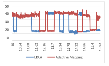 Figure 10 The variation of the PSNR for the different mapping algorithms: EDCA (blue)and adpatative (red)
Table 3 Average PSNR and number of packets lost for each mapping algorithm.
| Mapping algorithm | Average PSNR | Number of lost packets | |||
| Layer-1frame | Layer-2frame | Layer-3frame | Total | ||
| EDCA | 23.86 | 19 | 19 | 37 | 75 |
| Adaptative mapping | 31.71 | 2 | 3 | 6 | 11 |
Due to the classification of video packets, and the usage of IEEE 802.11p standard resources, packet losses may be minimized, and the most critical video packets can be protected. For example, if a technique is more efficient, the overall number of lost packets reduces dramatically. The adaptive technique has a packet loss rate of 11 compared to 75 for the EDCA method. The EDCA’s packet loss is evenly distributed throughout the several tiers. The unbalance also depends on the relevance of the layer for both static and adaptive approaches. There are just two missed packets when using the adaptive method instead of the EDCA’s 19 when using the static approach. The adaptive technique, on the other hand, can better secure the most critical layers’ packets ensuring a better video quality as seen by the average PSNR of a video sequence.
5. Conclusion
In this paper, we have investigated the combined effect of the network density and the image blitheness on the PSNR performance. We created a variety of network models with varied network densities, and the assessment results revealed several intriguing facts, including the fact that PSNR performance degrades as the network density grows. It is also discovered that the PSNR suffers a significant reduction when the network density rises due to packet loss.
Video transmission in a vehicular environment is affected by various forms of losses, which results in packet loss and greatly affects the perception of perceived quality. The real-time transmission of a live video feed via the VANET is a difficult task. However, the new HEVC coder shows more promising results and offers considerable advancements in video coding in a wireless setting compared to its predecessor. Adaptive algorithms are presented in this study.
Low-latency HEVC streaming over IEEE 802.11p vehicular networks may now be improved using a new cross-layer map-ping approach. MAC layer application layer information is used in a cross-layer manner in the suggested enhancement. Indeed, the method can optimally transport video packets based on information about the MAC layer buffer filling status, frame type, and temporal prediction video structure.
Simulation findings reveal that the suggested alternatives outperform the typical EDCA in many distinct situations and scenarios. In addition, a comparison of the suggested adaptive algorithm’s QoS and QoE results showed that it gives the best outcomes for the various HEVC temporal forecast structures.
The present AI encoding setup does not include any kind of categorization. As a result, our next step would be to look into a more efficient video packet classification algorithm for this kind of transmission. Also, packets that aren’t received in the allocated time aren’t included in the calculation. As a result, sending them through the network is a waste of time and bandwidth, therefore they can be eliminated at the transmitter. Hence an algorithm capable of doing so should be considered, an algorithm connects the queue buffering time, delay constraints at application level and end to end delay.
- M.G. W.L. Junior, D. Rosário, E. Cerqueira, L.A. Villas, “A game theory approach for platoon- based driving for multimedia transmission in VANETs,” Wirel. Commun. Mob. Comput., 2414658, 1– 11, 2018, doi:https://doi .org /10 .1155 /2018 /2414658.
- A.V.V. M. Jiau, S. Huang, J. Hwang, “Multimedia services in cloud-based vehicular networks,” IEEE Intell. Transport. Syst. Mag., 7(3), 62–79, 2015, doi:https://doi .org /10 .1109 /MITS .2015 .2417974.
- X.Z. M. Gerla, C. Wu, G. Pau, “Content distribution in VANETs, Veh.,” (Veh. Commun. 1(1), 3–12, 2014.
- R.S. C. Campolo, A. Molinaro, “From today’s VANETs to tomorrow’s plan-ning and the bets for the day after,” (Veh. Commun. 2(3), 158–171, 2015, doi:https://doi .org /10 .1016 /j .vehcom .2015 .06 .002.
- R.F.S. D. Perdana, “Performance comparison of IEEE 1609.4/802.11p and 802.11e with EDCA implementation in MAC sublayer,” in International Conference on Information Technology and Electrical Engineering (ICITEE), 285–290, 2013.
- T.W. G.J. Sullivan, J.R. Ohm, W.J. Han, “Overview of the high efficiency video coding (HEVC) standard,” IEEE Trans. Circuits Syst. Video Technol. 22(12), 1649–1668, 2012, doi:https://doi .org /10 .1109/TCSVT.2012 .2221191.
- H.D. I. Parvez, A. Rahmati, I. Guvenc, A.I. Sarwat, “A survey on low latency to-wards 5G: RAN RAN, core network and caching solutions,” IEEE Commun. Surv. Tutor, (1), 2018, doi:https://doi .org /10.1109 /COMST.2018 .2841349.
- E.C. C. Quadros, A. Santos, M. Gerla, “QoE-driven dissemination of real-time videos over vehicular networks,” Computer Communications, 91–92, 91–92, 2016.
- M.F. P. Gomes, C. Olaverri-Monreal, “Making vehicles transparent through V2V video streaming,” IEEE Trans. Intell. Transp. Syst, 13(2), 930–938, 2012, doi:https://doi .org /10 .1109 /TITS.2012 .2188289.
- T.H. R. Alieiev, A. Kwoczek, “Automotive requirements for future mobile networks,” IEEE MTT-S International Conference on Microwaves for In-Telligent Mobility (ICMIM), 1– 4, 2015.
- J.I.A. M. Oche, R.M. Noor, “Network centric QoS performance evaluation of IPTV transmission quality over vanets,” Comput. Commun, 61, 34–47, 2015, doi:https://doi .org /10 .1016 /j.comcom .2014 .12 .001.
- M.P.M. P. Pinol, A. Torres, O. Lopez, M. Martinez, “Evaluating HEVC video delivery in VANET scenarios,” IFIP Wireless Days (WD), (Nov. 2013), 2013.
- Y.J. A. Torres, C.T. Calafate, J.-C. Cano, P. Manzoni, “Evaluation of flooding schemes for real- time video transmission in VANETs.”
- D.A. I. Zaimi, Z.S. Houssaini, A. Boushaba, M. Oumsis, “An evaluation of routing protocols for vehicular ad-hoc network considering the video stream,” Wirel. Pers. Commun., 98(1), 945–981, 2018, doi:https://doi.org/10.1007/s11277- 017-4903-y.
- G.J.S. C. Rosewarne, B. Bross, M. Naccari, K. Sharman, “High efficiency video coding (HEVC) test model 16 (hm 16) improved encoder description update 9,” in document: Jctvc-ab1002, joint collaborative team on video coding (jct-vc) of itu-t sg16 wp3 and iso/iec jtc1/sc29/wg11 28th meeting, 15–21, 2017.
- M. Wien, “High Efficiency Video Coding: Coding Tools and Specification,” Springer-Verlag, 2015.
- H.Y.W. C.H. Mai, Y.C. Huang, “Cross-layer adaptive H.264/AVC streaming over IEEE 802.11e experimental testbed,” in IEEE 71st Vehicular Technology Conference, 1–5, 2010.
- D.W. Q. Chen, “Delay-rate-distortion model for real-time video communica-tion,” IEEE Trans. Circuits Syst. Video Technol., 22(12), 1376–1394, 2015, doi:https://doi .org /10 .1109/TCSVT.2015 .2389391.
- Y.I. G. Kokkonis, K.E. Psannis, M. Roumeliotis, “Efficient algorithm for transferring a real-time HEVC stream with haptic data through the internet,” J. Real-Time Image Process., 343–355, 2016, doi:https://doi .org /10 .1007 /s11554 -015 -0505 -7.
- X.S. C. Han, M. Dianati, R. Tafazolli, R. Kernchen, “Analytical study of the IEEE 802.11p MAC sublayer in vehicular networks,” IEEE Trans. Intell. Transp. Syst., 13(2), 873–886, doi:https://doi.org/10.1109/TITS.2012.2183366.
- V. Srivastava, M. Motani, “Cross-layer design: a survey and the road ahead,” IEEE Commun. Mag, 43(12), 112–119, 2005, doi:https://doi .org /10 .1109 /MCOM .2005 .1561928.
- G.J. van R. M.J. Booysen, S. Zeadally, “Survey of media access control pro-tocols for vehicular ad hoc networks,” IET Commun., 5(11), 1619–1631, 2011, doi:https://doi .org /10 .1049/iet -com .2011.0085.
- Intelligent transport systems (ITS); access layer specification for intelligent transport systems operating in the 5 GHz frequency band, ETSI EN 302 663, 1.2.1, 1–24, 2013.
- A. Festag, “Standards for vehicular communication—from IEEE 802.11p to 5G,” E&I, Elektrotech. Inf.Tech, 132(7), 409–416, 2015.
- IEEE standard for wireless access in vehicular environments (WAVE)–multi-channel operation, IEEE Std, 1609.4, 1–89, 2010, doi:https://doi.org /10 .1109 /IEEESTD .2011.5712769.
- R. Zhang, L. Cai, J. Pan, “Resource Management for Multimedia Services in High Data Rate Wireless Networks,” Springer-Verlag, 2017.
- IEEE standard for wireless access in vehicular environments (WAVE)–multichannel operation, IEEE Std, 1609.4–201, 1–89, 2011, doi:https://doi.org/10.1109/IEEESTD.2011.5712769.