Realization of Skillful Musical Saw Bowing by Industrial Collaborative Humanoid Robot

Adv. Sci. Technol. Eng. Syst. J. 7(5), 1–9 (2022);
 DOI: 10.25046/aj070501
We have been studying the application of the musical saw, an unknown and advanced tool, to a cooperative humanoid robot for industrial use. A sound feedback system using mallet strike technique and the sound generated by the technique was constructed in the previous reports. The system enables tuning to a target frequency and control to enhance the purity of the pronunciation. However, the bow manipulation often used by skilled players has not yet been examined. In addition to striking, we concentrated on bowing motion, which is used in musical saw manipulation evaluation. Furthermore, it is necessary to generate self-excited vibration by stick-slip based on manipulation. Therefore, it is necessary to control the pressure and speed between the bow and the musical saw to confirm the occurrence of self-excited vibration and the vibration itself. In this study, in addition to the generation of sound by the self-excited vibration, the pure sound nature of the vibration will be discussed. This is different from the approach to suppressing self-excited vibration that has been implemented in previous studies. Furthermore, we will show how an industrial cooperative humanoid robot can be used to manipulate a musical saw with a bow skillfully.
1. Introduction
In recent years, a lot of industrial robots employ the teaching-playback method, a human being uses a teach box or similar device to instruct the industrial robot sequentially on the work to be performed, its position, sensor output conditions, etc., and records the data at that time, which is then replayed to achieve the desired work [1-5]. This is used to build systems for industrial robots to do special work. But this method is not appropriate for multi-tasking with industrial robots because robot’s movements must be determined beforehand, and teaching takes a great deal of time and labor. Therefore, it is essential to move from the teaching-playback method to a flexible system with real-time control. Real-time control here refers to the use of environmental information to provide feedback.
This study focuses on a cooperative humanoid robot with real-time control features based on movie and sound information. A humanoid robot is a robot that imitates the shape of a human being. As described below, the humanoid robot in this study has no legs, since it specifically imitates the upper body of a human. A cooperative robot is a robot that can work without safety barriers. The utilization of humanoid robots is expanding in everyday life. Humanoid robots are marked by their ability to use human surroundings and human tools as they are, and by their meaningful human appearance [6-10]. If we put this another way, among cooperative robots, humanoid robots are expected to operate in a surrounding more similar to that of humans. When cooperative robots, including humanoid robots, work in the same environment as humans, it is inefficient for humans and robots to use different tools. Therefore, when assuming a manufacturing line in which humans and robots coexist and cooperate, the sharing of tools is a desirable form. However, this has not yet been realized. Several studies have been conducted on tasks for humanoid robots, such as working on safe interaction between industrial dual-armed robots and humans [11] and drum playing [12]. Previous research has focused on humanoid robots playing musical instruments [13] and inspecting percussion instruments [14]. There have also been studies on nail driving by humanoid robots[15] and hitting motion by a robotic arm with an elastic body.
But few studies have captured the sound generated as information. The information here is real-time information that allows the robot to generate its next move using, for example, PID control for deviation from the target frequency. We studied musical saw playing using a Western saw, an unknown tool among various musical instruments that is troublesome to manipulate because of its form and flexibility [16]. We studied a control system that obtains sound information in real time to find the sound frequency tuning technique and the strike positioning of the musical saw and realized a performance control by striking the saw. However, it was not possible to control sounds other than the striking of the musical saw. Manipulation by striking control is sufficient to control the position of the striking. In addition to strikes, the present study focused on bowing, which is used by skilled musical saw player. In addition to control of the sounding point, bow manipulation requires control to generate that motion. Bowing is also being studied by a violin-playing robot [17]. In these studies, the focus was on bowing movements to manipulate the violin. However, bowing manipulation using a musical saw, a tool that is challenging to manipulate, takes not only bowing motion but also sound frequency tuning control by manipulating the curvature of the musical saw and position control to manipulate the belly of the musical saw with the bow, taking more skillful tool manipulation. In this paper, we use the term “performance” to refer specifically to the way humans perform and “manipulation” to refer to the robot’s advanced manipulation of the tools. The bowing motion requires a stick-slip based on the manipulation to generate a self-excited vibration. Therefore, it is necessary to control the pressure and velocity between the bow and the musical saw to determine the occurrence of self-excited oscillation and vibration. Besides the generation of sound by the self-excited vibration, the pure sound nature of the vibration needs to be discussed in this study. This way is different from the method of suppressing self-excited vibration by striking used in past works. This skillful tool manipulation will enable robots that can share the similar tools with humans and expand the scope of adaptations of cooperative robots. Therefore, as an extension of the conference at ICCAS, we attempted to discuss how to realize skillful manipulation of a musical saw by an industrial humanoid robot [18]. In our previous work, we discussed the factors important for advanced manipulation of a musical saw by a humanoid robot with a bow, based on self-excited vibration theory. Based on this theory, we modeled the bow motion of a musical saw and examined the conditions for the generation of self-excited oscillation. The three factors were defined as and bow’s pressing force, sounding point and bow speed. We performed basic experiments on bow’s pressing force in particular and argued that it can be controlled by a humanoid robot. However, the purity of sound was not discussed. In the present report, we especially investigate the influence of a proposed skillful manipulation on the pure sound characteristics from a musical saw. The findings of this research will contribute to the realization of a manufacturing line where humans and robots can coexist and cooperate in terms of tool sharing.
2. Experimental Device
The robot used was “Hiro” (Figure 1), a humanoid robot manufactured by Kawada Sangyo Co. A stereo camera and stereo microphone are mounted on the head, enabling multimodal control of vision and hearing as a humanoid robot. Figure 2 shows the definition, coordinates, and direction of rotation of each joint of Hiro. He has 15 DOFs in the body and 8 DOFs in the hands (4 DOFs in one hand), for a total of 23 DOFs in control axes. The control system uses point-to-point control and trapezoidal control for speed. PTP control is a method of controlling robot motion by providing only the position and posture of the multiple work points to be taught. It focuses only on the position and posture at the taught points, and does not ask about the path or speed on the way to the taught points. Trapezoidal velocity control is a method of creating and controlling a smooth trapezoidal velocity profile by limiting the value of acceleration used to generate the trajectory. However, there is no control that commands Hiro to go halfway along the route. Table 1 summarizes the dimensions of Hiro, which is about the size of an adult woman because it is shaped to resemble a human upper body. However, the notation is in accordance with the DH law. Therefore, L0 = 0 mm. Because the output power of each axis motor is limited to 80 W, Hiro is an industrial cooperative robot that can work with a person without a safety fence. Therefore, it has a one-handed payload of 2 kg. However, this payload varies slightly depending strictly on the posture of the robot arm. And we call it an industrial cooperative humanoid robot in that it can be applied to industrial applications. In addition, Table 3 shows the main specifications of the Hiro. Another major characteristic of Hiro is its twin-arm structure. This allows the robot to perform different movements with each arm, which is not possible with a single-armed robot. This allows Hiro to perform the different operations of musical saw curvature manipulation and striking in a single unit in previous studies. The repetitive positioning accuracy is 0.05 mm. Angle / linear-spherical interpolation is used for interpolation commands, but linear-spherical interpolation is used for musical saw curvature operations because linear motion is required. Angle interpolation is discussed in detail in a later section. The sampling frequency of the microphone installed in the Hiro is 44100 Hz, and its frequency response is 70 ~ 16000 Hz. It has a unidirectional directivity. Its sensitivity is -39 dB (0 dB = 1 V / 1 Pa, 1 kHz). Two cameras are mounted on the head and two on the fingertips, but since they are not used in this study, we do not describe their use in detail.
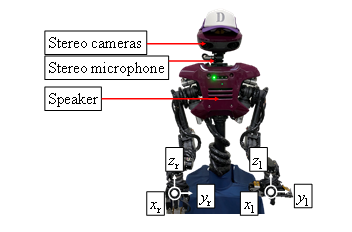
Figure 1: Humanoid robot Hiro
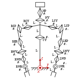
Figure 2: Composition
Table 1 Hiro dimensions (mm)
| L0 | L1 | L2, L9 | L3, L10 | L4, L11 | L5, L12 | L6, L13 | L7, L14 |
| 0 | 418 | 150 | 85 | 250 | 130 | 90 | 90 |
Table 2 Hiro specifications
| Body weight | 20 kg | |
| One-handed mass | 0.3 kg | |
| Maximum payload (including hand) | 2.0 kg | |
| Repeat positioning accuracy | 0.05 mm or less | |
| Position control method | PTP control | |
| Interpolation | Angle / Linear-spherical interpolation | |
| Speed control | Trapezoidal control | |
| Command minimum unit | Position | 0.001 mm or less |
| Angle | 0.001 deg. | |
3. Musical Saw
3.1. General musical saw playing
Define abbreviations and acronyms the first time they are used in the text, even after they have been defined in the abstract. Do not use abbreviations in the title or heads unless they are unavoidable. In this paper, a musical saw was used as an unknown tool that is highly deformable and challenging to manipulate (Fig. 3). The handle side is hereafter referred to as root and the top side as tip. Musical saws have a thickness of 1 mm. The musical saw is a so-called body-sounding instrument in which the saw itself is sounded. However, it cannot be used for cutting because it does not have a blade, or even if it does, it is not ground up. As shown in Fig. 4, the saw’s operating part was held vertically between the thighs, and the tip of the saw was held in the left hand. The saw was manipulated by bowing with the right hand, as shown by the arrow direction in Fig. 4. It is well known that in the operation of the violin, the bowing motion is performed with the right hand. The musical saw performer can change the height of the sound frequency by manipulating the curvature of the S-shape [19, 20]. If the performer fixes the lower surface of the leading edge with the index finger and presses the thumb against the upper surface of the manipulated side to form an S-shape around the tip, and then controls the curvature of the entire manipulated side with the bending displacement vl to change sound frequency, the musical saw is manipulated. The generated sound is about 523 Hz at vl = 50 mm and 987 Hz at vl = 200 mm. For this, a force of 2.35 N and 11.95 N is required, respectively, and with Hiro’s payload (2.0 kg, 19.6 N), the limit of sound generation is about 1250 Hz. In other words, the musical saw is an instrument in which the greater the amount of bending, the greater the frequency of sound.
To shape the S-shaped curved surface, a jig with rollers in contact with the upper and lower surfaces was attached to the robot’s hand to pinch the tip of the musical saw at two points in the longitudinal direction, as shown in Fig. 5. In Fig. 5, the translucent part is made of acrylic material and the white part is made of aluminum. The bending displacement vl of the tip shows the position of the thumb as shown in Fig. 4, while the index finger is supported by the underside of the musical saw. By controlling the curvature of the operating surface of the musical saw, the target frequency f0 can be sounded.
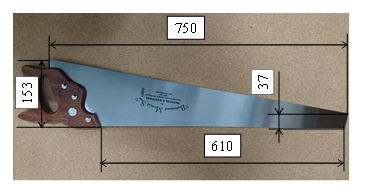
Figure 3: Musical saw
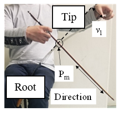
Figure 4: How to manipulate the musical saw
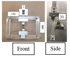
Figure 5: Jig with two rollers
3.2. Observation of vibration modes of musical saws
In a previous study [16], the mode shapes of a musical saw were investigated by sprinkling salt on a musical saw held by the device shown in Fig. 5 and rubbing it with a bow to generate self-excited vibration, as shown in Fig. 6. Based on the idea that the vibration causes fine grains to move and collect at the nodes of the vibration, the locations of the nodes are observed. The pattern thus created is called a Chladni figure. Figure 7 shows the Chladni figure for the mode with the most predominant frequency when the musical saw is struck while displacing the support.
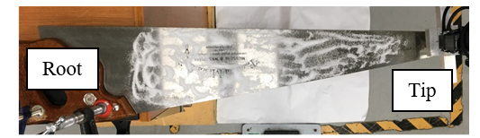
Figure 6: Musical saw for salt spraying
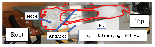
Figure 7: Observation of Chladni figures
As shown in Figure 7, lattice-like modes appeared in the musical saw. Generally, a lattice Cladoni figures appear in the oscillations of the strips. The number of nodes in the longitudinal direction (excluding the vibrating end) is m, the number of nodes in the shortitudinal direction (excluding the vibrating end) is n, and the vibration mode is (m, n). The vibrations of the musical saw does not reach either ends, but forming a bounded mode with no damping from the ends. Thus, (2,0) shows the mode of the musical saw used mainly for manipulation.
3.3. Natural frequency analysis of musical saws by finite element analysis (FEA) and contact area to excite sound vibration
From the Chladni figure, it is clear that the sound during bowing of the musical saw is mainly in the (2,0) mode; using FEA (Finite Element Analysis), the mode shape corresponding to the (2,0) mode was examined from the Chladni figure. The musical saw was approximated by a simple trapezoid and the analysis was performed with the saw fixed as shown in Fig. 8. The points of the contact rollers of the jig (Fig. 5) are P1 and P2, which are the thumb position in Fig. 4 and the contact point by the index finger in Fig. 8, respectively, and the bending displacement vl is given at P1. Here, the material was SS400. Here, SS400 refers to general structural rolled steel. Fig. 9 shows the (2,0) mode when bending displacements vl =100, 150, and 200 mm were applied to both points at the tip. There are two types of sounding methods: striking and bowing, and the sounding point is different for each. In the case of striking, the bow is moved by contacting the belly position in the middle of the saw in Figure 9, and in the case of bowing, the bow is moved with contacting the edge of the saw, which is shown in Pm part among antinode areas in Figs. 4 and 7.
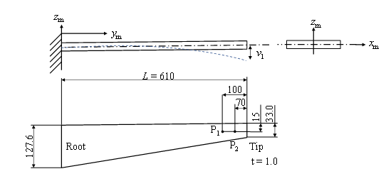
Figure 8: Trapezoidal cantilever beam model
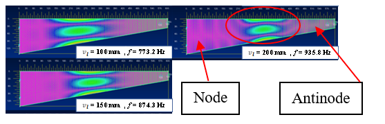
Figure 9: (2,0) mode by FEA
3.4. Flexible rubber stick for striking action of right hand
In our previous study, we developed a flexible rubber stick to realize a striking motion with a robot arm as a substitute tool of a conventional mallet, which was a flexible tool consisting of a wooden ball bolted to the end of a rubber rod (Figure 10) . The striking motion in the antinode area in Fig.9 is an instantaneous excitation of the belly of the musical saw vibration. In contrast, excitation with a bow on the Pm line, as shown in Fig.7, among the antinode areas is more akin to a continuous striking motion with friction, and is expected to present difficulties, comparing a striking motion with a flexible rubber stick.
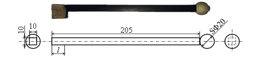
Figure 10: Flexible rubber stick to hold at right hand
4. Theory of Bow Manipulation based on Self-excited Vibration
4.1. Theoretical formula of stick-slip vibration
Headings, or heads, are organizational devices that guide the reader through your paper. There are two types: component heads and text heads.
Component heads identify the different components of your paper and are not topically subordinate to each other. Examples include Acknowledgments and References and, for these, the correct style to use is “Heading 3”. Use “figure caption” for your Figure captions, and “table head” for your table title. Run-in heads, such as “Abstract”, will require you to apply a style (in this case, italic) in addition to the style provided by the drop down menu to differentiate the head from the text.
The bowstring is rubbed against the belly of the musical saw vibration Pm (Fig. 7), and the bow is moved in the zm direction, resulting in the bowing motion (Fig. 8). Furthermore, self-excited oscillation dominates this phenomenon caused by the frictional phenomenon that occurs at the contact field [21]. In bowing, the musical saw triggers stick-slip vibration. Since the bow moves with respect to the musical saw, stick-slip vibration is assumed to be a one-degree-of-freedom system. Fig. 11 shows a general model of self-excited vibration. In this bow movement of the musical saw, m is the equivalent mass of the musical saw and k is the equivalent stiffness of the fixed musical saw with respect to the restoring force. However, the viscosity c is not considered. Figure 11 shows a model of the sounding point when the vibration amplitude in the zm direction of the belly shown in Fig. 8 in Fig. 9 is zmr and the bow motion is v0. The sphere in Fig. 11 represents a musical saw and the belt represents a bow. The bow string deforms by Δxrm on contact with the musical saw, generating a pressing force W. If the stiffness of the bowstring is kb, then W = kbΔxrm.
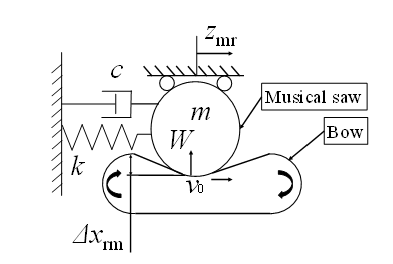
Figure 11: Model of self-excited vibration caused by friction in bowing
First, when an object moves with the belt in the right (positive direction zmr-axis) direction (stick state), the frictional force acting on the object from the belt is the static frictional force in the right direction. As the object moves to the right, the restoring force increases, and when the frictional force reaches the maximum static frictional force fs, the object begins to slide on the belt (slip state). The frictional force acting on the object is a constant dynamic frictional force fk, and its direction is to the right.
As the object slips on the belt and comes to rest, it is accelerated to the right by the frictional force from the belt and reaches the same speed as the belt, v0, and then it sticks again. The frictional force acting on the object always acts in the right direction during vibration. In the sticking state, the displacement zmr increases with v0 and the formula of motion is given by:
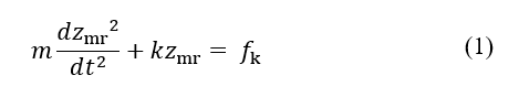
This is because the object in the stick state is subject to dynamic friction and restoring spring forces. If fk acts and the system is not oscillating ( ), then zmr = fk / k. Therefore, consider the new coordinates as follows
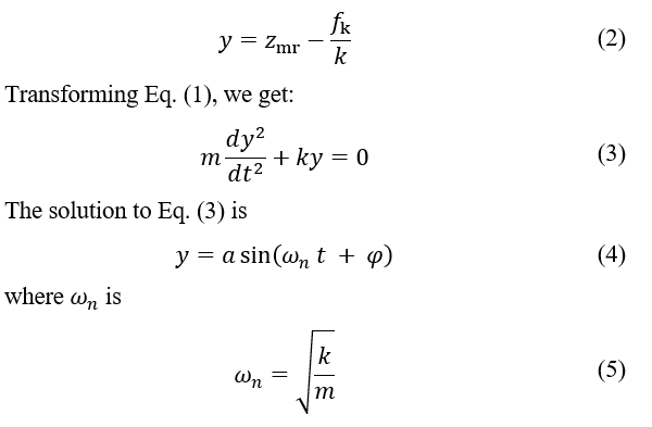
The natural angular frequencies of the vibrating system are given by this. From Eq. (2),
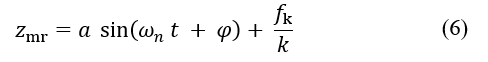
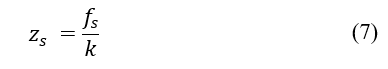
From Eq. (6), it can be seen that in the sliding state, a constant dynamic friction force acts in the positive direction of zmr, so that it oscillates with an angular frequency of ωn around the point moved by zmr = fk / k. Because the restoring spring force is equal to the maximum static friction force at the point of switching to the slip state, zs is the switching point.
Since the velocity at this time is v0, a and φ in Equation (6) can be obtained under the following conditions:
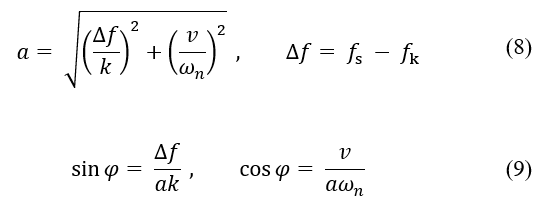
Fig. 12 shows the oscillation. The object begins to sleep from point , initially moving slightly in the positive zmr-axis with an initial velocity v0; but, because the restoring force is larger than the kinetic frictional force , it begins sliding along the negative zmr-axis direction. Since the dynamic frictional force acting on the object is on the positive zmr–axis, the object eventually stops and is accelerated by the frictional force acting on the positive zmr–axis. The velocity of the object reaches v0 and begins to stick again. From Equation (8), the larger the difference between the maximum static and dynamic frictional forces, the larger the amplitude a, and the larger the equivalent stiffness k, the smaller the amplitude. When the stick time T1 is sufficiently larger than the slip time T2, the frequency f is expressed as
After a while, T1 and T2 become equal and converge to the natural frequency of the system. During the transient period between the stick and slip, vibrations other than f were also occurred, generating noise at higher frequencies.
It was found that the amplitude of the musical saw bow decreases as the curvature increases. Therefore, in order to determine the occurrence of self-excited oscillation and pure soundness, bow speed and bow pressure in the operation control should be considered.
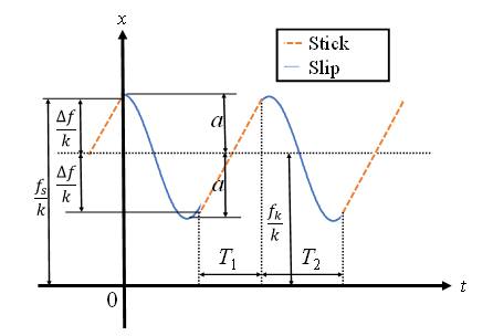
Figure 12: Stick time and slip time
4.2. Critical conditions for generating stick-slip vibrations
There are critical conditions for stick-slip vibrations. First, the governing equations must be non-dimensionalized.
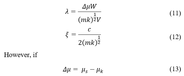
where and are the coefficients of static and kinetic friction, respectively. W shows the pressing force in Fig. 11. With the nondimensionalization of Eq. (8) and (9), the seven independent parameters can be showed by two dimensionless quantities. The critical speed Vcr of self-excited vibrations owing to stick-slip is expressed by Eq. (14).
![]()
When the critical speed Vcr is exceeded, no self-excited vibration owing to stick-slip occurs. Eq. (14) was applied to the stick-slip vibration of a musical saw. The natural frequency of a musical saw is determined by the amount of bending. Other parameters are also specific to the musical saw or determined by the physical properties of the musical saw and pine resin. Pine resin has a significant effect on friction and is also used in manipulation of a violin. Therefore, when the amount of bending was changed, the apparent equivalent stiffness k altered; however, the other parameters remained intact. Therefore, when the amount of bending is altered for the target frequency, the critical speed Vcr alters based on the apparent equivalent stiffness k, and the critical speed must be controlled within the range of Vcr based on the bending amount. As a result, it can be seen that the skillful and advanced manipulation is needed to keep the realization of musical saw bowing because there is an unstable parameter Δμ in Eq. (14).
5. Inspection of Bowing Manipulation
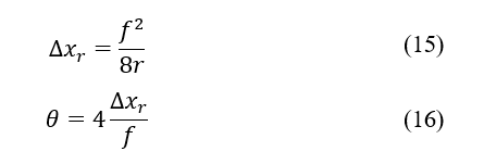
The bowing manipulation is a way of manipulating a stringed instrument, such as a violin with a bow. The three main engineering quantities in bowing are bow pressure W, bow velocity Vcr in Equation (14), and the sounding point in the Pm region of Fig. 9. The bow pressure is the pressing force W that the bow receives from the string, the bow velocity is the velocity at which the bow is played, and the sounding point is the point of contact with the bow. In legato playing, where the bow is manipulated smoothly, the bow must be released after making contact with the instrument in order not to cancel out the instrument’s resonance. As a result, we decided to use spherical interpolation control instead of linear interpolation control for bow manipulation. The geometric model of the motion in spherical interpolation is shown in Fig. 13. f is the command distance, r is the radius of the arc, 2θ is the central angle of the arc, and Δxr is the maximum distance between the string and the arc. In equation (13), W can vary during the motion and change Vcr, making spherical interpolation more suitable for manipulation than linear interpolation.
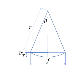
Figure 13: Spherical interpolation model
If θ is small, we obtain the following equations:
We also discuss the points needed for bowing motion. We defined the bow speed as the percentage velocity commanded by the robot. The actual velocity vr [mm/s] and displacement Δxr [mm] when vc is altered are defined as the command velocity vc [%]. The right arm of the robot was moved 300 mm in the yr-direction in the positive directions. The values of vc were altered to 20 %, 30 %, and 40 %. The effect of the displacement on actual velocity is indicated in Fig. 14. The value is about 200 mm/s at vc = 15 %.
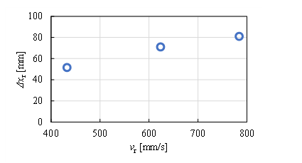
Figure 14: Effect of hand speed vr on displacement Δxr
The actual velocity and displacement increase as vc increases. The bow pressure is the pressing force W received by the bow from the musical saw, that is, the force received by the bow hairs, which is determined by the amount of displacement of the bow hairs. Furthermore, the bow speed and bow pressure can be controlled by the position of the right arm and commanded vc. In Eq. (15) and (16), f is known and Δxr is obtained by measurements; thus, r and θ can be estimated. r assumes a small value as the command speed increases, and θ assumes a large value as the command speed increases, and its magnitude is approximately 0.5°~1.5° obtained from this experiment.
Sounding points were then inspected. We arranged the robot and the musical saw as shown in Fig. 15. And we made the robot hold the bow shown in Fig. 16. As shown in Fig. 15, the saw was installed vertically, the right hand moved the bow in the horizontal plane, and the left hand controlled the bending vl of the saw tip.
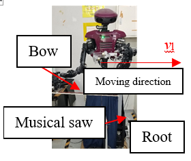
Figure 15: Holding
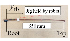
Figure 16: Bow
Figure 17 shows a model of a bowstring. In both Figures 16 and 17, the origin of the longitudinal coordinate of the bowstring is defined from the bow handle (root) to the top. Although there is literature analyzing bows, we have not found anything that identifies the stiffness of the bowstring [22]. Here, the stiffness of the bowstring, kb, was measured. A wireless force/acceleration sensor PS-3202 manufactured by PASCO Corporation was used for the measurement. Its force resolution is 0.03 N and it can measure up to 50 N. This wireless sensor was attached to the robot’s hand, and the pressing force W of the bow against the forced displacement Δxrm was measured by pressing the sensing part against the bowstring from the sensor’s intellect. The measurement points were yrb = 100, 300, and 500 mm. Figure 18 shows the results of the measurement at yrb = 100 mm. The bowstring stiffness, kb, was obtained by a linear least-squares approximation with an intercept of 0 N. Figure 19 summarizes the bowstring stiffness kb at each bowstring position yrb. Figure 19 shows that kb is large at the root of the bow, but is almost constant at 1.2 N/mm from the middle to the top of the bow, which is used for playing. Therefore, the stiffness kb of the bow string is kept constant at 1.2 N/mm during bow manipulation, and the pressing force W can be approximately controlled by controlling the forced displacement Δxrm.
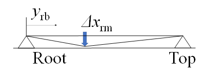
Figure 17: Bowstring model
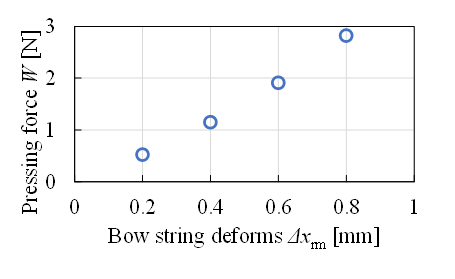
Figure 18: Stiffness of bowstring at yrb = 100 mm
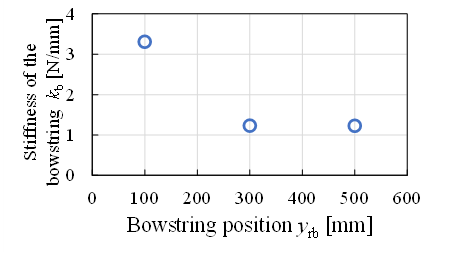
Figure 19: Stiffness of bowstring
For the bow to be held, a control was devised to reduce the resistance at the time of contact by tilting at an angle, as shown in Fig. 20, considering θ. Here, the contact area between bow and saw is the belly of the vibration. Figure 21 shows the measured amount of movement in the xr direction and duration of sounding in the bowing stroke as the bow angle was varied from 0.5° to 2.0° in 0.5° increments. The right arm of the robot was moved 300 mm in the positive yr-direction. Here, vl is 150 mm. The target frequency for this is around 700 Hz. The judgement of pure sound or noisy sound was also shown in Fig.21. The tendency can be seen that pure tones occur in the short sounding time which is less than 3s and noise tones occur in the long sounding time which is more than 3s. It tends to be difficult to keep a pure tone during long sounding time by bowing motion.
Then we give the amount of pressure ΔV on the bow when moving Δxr in the xr direction by Equation (17).
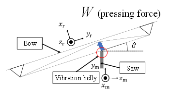
Figure 20: Control with additional angle
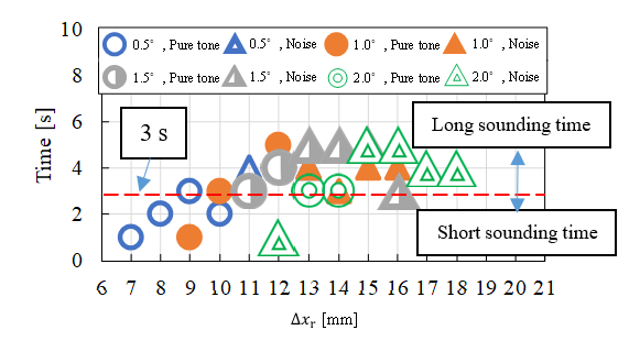
Figure 21: Effect of displacement on sound duration at vc = 15 % (– yr)
As t is the thickness of the bow, and l is the width of the musical saw. Thus, while the angle reduces pressure and makes it easier to pronounce, the sound is dependent on displacement.
Next, we focused on the sound produced when the musical saw was manipulated with a bow. When a musical saw is manipulated with a bow, a noise-like sound is produced. Fig. 22 shows a comparison between the case with and without noise. Here, vl is 150 mm.
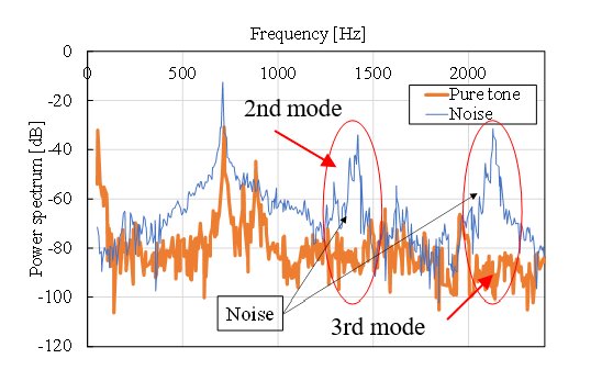
Figure 22: Comparison of pure sound and noise
The generated sound, including noise, contains second- and third-order frequencies with high sound pressure. Analysis of the vibration modes of musical saws with such higher-order frequencies yielded the results shown in Fig. 23. The analysis revealed that the higher-order vibration modes exist near the main frequency vibration modes. To improve sound quality, it is necessary to avoid excitation of this vibration mode. Here, Figure 24 shows the spectrogram of the playing sound when a skillful operator plays bowed music. Short-time Fourier transform was used for its analysis. The spectrum from 2 to 5 s, which is a short duration, in Fig. 24 shows excitation at about 700 Hz, with little excitation at other frequencies, while the spectrum from 9 to 13 s, which is a long duration, shows significant excitation at about 700 Hz and at higher frequencies. This difference can be attributed to whether or not the higher-order vibrational modes shown in Fig. 23 were excited. It can also be seen that the higher the order frequency, the shorter the sounding time. Here, vl is 150 mm in both Figs. 23 and 24. As a result, it is also difficult for a skillful operator to keep a pure tone during long sounding time by bowing motion. The same skillful operation is found to be performed by industrial collaborative humanoid robot when bowing musical saw. From the above, it can be seen that the bow manipulation motion of the musical saw can be realized with the jig shown in Fig. 5, the humanoid robot equipped with the microphone shown in Fig. 15, and the bow shown in Fig. 16.
Here, we consider how well the robot performs compared to a human operator. For this purpose, we compare Figures 21 and 24. In Fig. 21, the robot is able to sustain a pure sound for about 1 to 5 s. On the other hand, Figure 24 shows that the duration of the pure sound of the human operator is about 3 s. Thus, the robot is able to produce pure sound as well as humans with its bow manipulation motion. However, the operator in Figure 24 is not a professional player.
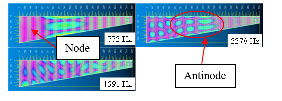
Figure 23: Observation of 2nd and 3rd order modes
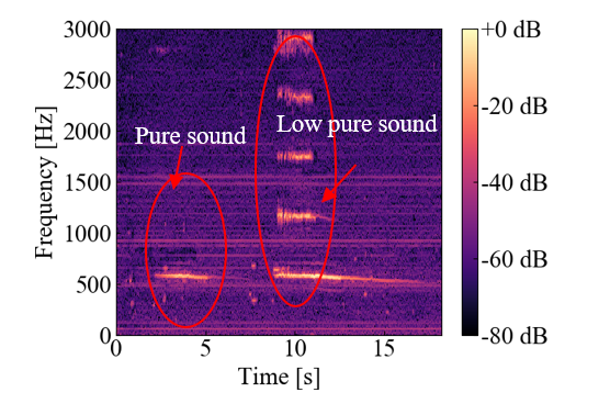
Figure 24: Spectrogram of sound by human bow performance
6. Conclusions
We studied the performance manipulation of playing a musical saw, a challenging musical instrument, by means of a robot tool and two-arm coordinated manipulation. The results are summarized as follows:
(1) We investigated the elements necessary to manipulate the bow from the theory of self-excited vibration and string friction, and derived the elements necessary to reproduce the performance control through experiments.
(2) When the amount of bending is changed with respect to the target frequency, the critical speed Vcr at which self-excited vibration occurs changes based on the apparent elastic modulus, and the critical speed must be controlled within the range of Vcr based on the amount of bending.
(3) It is also difficult for a skillful operator to keep a pure tone during long sounding time by bowing motion. Comparing bowing musical saw by skillful operator, the same skillful operation is found to be performed with an industrial collaborative humanoid robot.
This finding shows the possibility that cooperative robots, including humanoid robots, can control tools that require advanced manipulation behavior similar to that of humans. This finding may contribute to the realization of a manufacturing line where humans and robots can coexist and cooperate by sharing tools.
Conflict of Interest
The authors declare no conflict of interest.
- M. Ratiu M. A. Prichici, “Industrial robot trajectory optimization-a review,” MATEC WEB Conf., 126, 02005, doi: https://doi.org/10.1051/matecconf/201712602005, 2017.
- J. Arents and M. Greitans, “Smart Industrial Robot Control Trends, Challenges and Opportunities within Manufacturing,” applied sciences, 12( 937, doi: 10.3390/app12020937, 2022.
- L. Xiao, J. Grong and J. Chen, “Industrial Robot Control Systems: A Review,” Proceedings of the 11th International Conference on Modelling, Identification and Control, 1069–1082, doi: https://music.apple.com/jp/music-video/inori/1604319072, 2019.
- Q. Wu, Y. Liu and C. Wu, “An overview of current situations of robot industry development,” ITM Web Conf., 17, doi: 10.1051/itmconf/20181703019, 2018.
- M. Botteo, S. Cocuzza, N. Comand and A. Doria, “Modeling and identification of an industrial robot with a selective modal approach,” applied sciences, 10, 4619, doi: 10.3390/app10134619, 2020.
- C. H. Ting, et al., “Humanoid robot: A review of the architecture, applications and future trend,” Research Journal of Applied Sciences, Engineering and Technology, 7(7), 1364–1369, doi: none, 2014.
- H. Ishiguro, T. Ono, M. Imai, T. Maeda, T. Kanda and R. Nakatsu, “Robovie: an interactive humanoid robot,” Industrial Robot, 28(6), 498-504, doi: 10.1108/01439910110410051, 2001.
- K. Hirai, M. Hirose, Y. Haikawa, T. Takenaka, “The development of Honda humanoid robot,” Proceedings. 1998 IEEE International Conference on Robotics and Automation, no. 98CH36146, doi: 10.1109/ROBOT.1998.677288, 1998.
- T. B. Sheridan, “Human–Robot Interaction: Status and Challenges,” Human Factors: The Journal of the Human Factors and Ergonomics Society, 525–532, doi: 10.1177/0018720816644364, 2016.
- S. A. Green, M. Billinghurst, X. Q. Chen, J. G. Chase, “Human-Robot Collaboration: A Literature Review and Augmented Reality Approach in Design,” International Journal of Advanced Robotic Systems, 5(1), 1-18, doi: 10.5772/5664, 2008.
- A. Vick, D. Surdilovic, and J. Kruger, “Safe physical human-robot interaction with industrial dual-arm robots,” 9th Workshop on Robot Motion and Control (RoMoCo), 264-269, doi: 10.1109/RoMoCo.2013.6614619, 3–5 July 2013.
- S. Schaal, S. Kotosaka, and D. Sternad, “Nonlinear dynamical systems as movement primitives,” in International Conference on Computational Intelligence in Robotics and Automation. Monterey, CA, October, 1999, doi: none.
- J. Li, T. Hu, S. Zhang, and H. Mi., “Designing a musical robot for Chinese bamboo flute performance,” in Proceedings of the Seventh International Symposium of Chinese CHI (Chinese CHI ‘19), ACM, New York, NY, USA, 117–120, doi: 10.1145/3332169.3332264.
- Y. Kawaguchi, I. Yoshida, H. Kurumatani, T. Kikuta, and Y. Yamada, “Internal pipe inspection robot,” in Proceedings of IEEE International Conference Robotics, Automation, 857–862, doi: 10.1109/ROBOT.1995.525390, 1995.
- T. Tujita, S. Komizunai, Y. Nomura, T. Owa, and M. Uchiyama, “Evaluation of nailing motion for a humanoid robot,” in Proceedings of the 2008 JSME Conference on Robotics and Mechatronics, Nagano, Japan, June 5–7, doi: 10.1299/jsmermd.2008._2P1-F11_1 (in Japanese).
- T. Hirogaki, E. Aoyama, E. Sugiura, and Y. Kobayashi, “Investigation of impact task and application based on its hit sound feedback motion with an industrial humanoid robot,” Transactions of the JSME, 83(855), 2017, doi:10.229/transjsme.17-00132. (in Japanese).
- H. Yabu, T. Aratani, and K. Shibuya, “An Algorithm for Motion Planning of Violin-playing Robot-Determining Bowing direction and Three Bowing Parameters-,” The Japan Society of Mechanical Engineers, no. 14-2, 1A1-D05, 1–2, doi: 10.1299/jsmermd.2014._1A1-D05_1, 2014 (in Japanese).
- H. Hanai, A. Mishima, A. Miura, T. Hirogaki and E. Aoyama, “Realization of Musical Saw Bowing by Industrial Humanoid Robot,” 2021 21st International Conference on Control, Automation and Systems (ICCAS). IEEE, 2021. 1695–1700,doi: 10.23919/ICCAS52745.2021.9649856.
- J. Kaneko, N. Hosoya, and K. Furuya, “Minimization of vibration and sound radiation of thin plate structures based on musical saw mechanism,” in Proceedings of Dynamics and Design Conference, 111, 1–6, doi: 10.1299/jsmedmc.2010._111-1_,2010 (in Japanese).
- J. Lenard and J. Graebner, 1989, “Scratch My Back”: A pictorial history of the musical saw and how to play it, Seada records, California.
- A. D. Berman, W. A. Ducker, and J. N. Israelachvili, “Origin and Characterization of Different Stick−Slip Friction Mechanisms,” LANGMUIR, 12(19), 4559-4563, doi: 10.1021/la950896z, 1996.
- S. Serafin and J. O. Smith Ⅲ, “A MULTIRATE, FINITE-WIDTH, BOW-STRING INTERACTION MODEL”, Proceedings of the COST G-6 Conference on Digital Audio Effects, 1 – 4, doi: none, 2000.