An Improved Model to Analyze the Impact of Cyber-Attacks on Power Systems

Adv. Sci. Technol. Eng. Syst. J. 7(5), 27–34 (2022);
 DOI: 10.25046/aj070504
In this paper, an improved model has been proposed for investigating the impact of cyber-attacks on power systems regarding frequency disturbances and voltage disruption while changing the load called ICAPS. The proposed ICAPS model is formulated by five different controllers, such as LFC, AGC, AGC-PID, AVR, and AVR-PID, implemented in two sets of the system model. Specifically, a stable limit of the speed regulation of LFC, integral controller gain of AGC, and amplifier gain of AVR are determined from their characteristic equations derived from the Routh-Hurwitz array. In contrast, the Proportional-Integral-Derivative (PID) controller gains for AGC-PID and AVR-PID are determined using the tuning process. The key aspect of this paper is to obtain the impact of cyber-attacks on the power system in terms of frequency disturbances and voltage disruptions while changing the load. According to our knowledge, no one has considered these issues at a time. In order to evaluate the proposed ICAPS model and how it works, a series of experiments was conducted using the MATLAB Simulink tool. The simulation results are presented in this paper in terms of frequency deviation and voltage disruption (i.e., positive and negative biased cyber-attack) and system oscillations. Finally, the simulation results successfully identified the most severe attack in this model to prevent the power system from unstable conditions.
1. Introduction
The modern power system industry uses supreme technological innovation that enables more adaptable and efficient access to the system structure. In addition, the reliability and security of information communication technology (ICT) and digital computer techniques are crucial for the operation of power systems, which increases the risk of cyber-attacks. Due to cyber-attack, the cyber-vulnerable components of the power system and the effects of cyber-attack should be adequately analyzed [1]-[3].
The advanced control loop, sensor and communication networks are the cyber component of the power plant [4]. The sensors collect data for various parameters, which are sent to the controller to ensure stability of the power system [5]. Data is transferred using the communication network, which is one of the cyber-vulnerable components of the power system. An attacker can get it while sending data from the sensing department to the control department at the power station. The attacker can gain control over the automatic controller of a power plant after accessing confidential information. Ultimately, any change to the controller actions may create malicious data accessing in the controller, which disrupts the stability of the system.
However, in order to investigate the impact of cyber-attack on the power system, a few works have been done in the literature (e.g., [6]-[9] ). Specifically, in [6], the authors have discussed about the infrastructure of power system for identifying vulnerabilities. After that, a framework has been proposed to overcome the unstable condition of power system. Furthermore, the effect of cyber-attack on wind farms and power system networks that is also investigated in [7]. On the other hand, an anomaly detection technique has been proposed in [8] as a countermeasure against the effect of faulty data injection on AGC. The authors have investigated the impact of cyber-attack to AGC loop in the power system in [9]. It is noted that the reliability of the power system is an important factor in assessing cyber-security threats. That’s why, the impact of such threats need to be estimated upon the cost of the whole power system [10]. Finally, it can be concluded that, although the existing techniques (e.g., LFC, AGC) tried to investigate the impact of cyber-attacks properly, they failed to achieve significant improvement in such cases. Therefore, the effects of cyber-attacks should be properly analyzed to maintain the system’s stability.
However, to analyze the proper deviation to be provided the system stability, the impact of cyber-attacks on power system has been presented in this paper. The proposed ICAPS is combined by five different controllers, such as, LFC, AGC, AGC-PID, AVR and AVR-PID that are implemented in two different sets of the system models, among which the first three controllers are included for one set of power system models, whereas, the rest of two controllers are for different set of system models. This work focuses on the impact of cyber-attacks on system in terms of frequency and voltage disruptions during changing the load. It should be noted that, our proposed ICAPS can perform well to investigate the impact of cyber-attacks on the power system in terms of frequency disturbances and voltage disruption during changing the load. The most serious cyber-attack on power plant is also identified successfully.
The rest of the paper has been organized into three sections, among which proposed system investigated, in Section 2. Finally, Section 3 discusses the conclusion of our paper.
2. Proposed System Modelling
In this paper, the impact of cyber-attacks on power system has been proposed to ensure the system stability. To understand the proposed model ICAPS clearly, the following five subsections need to be discussed: (i) cyber-attack impacts on LFC, (ii) cyber-attack impacts on AGC, (iii) cyber-attack impacts on AGC-PID, (iv) cyber-attack impacts on AVR, and (v) cyber-attack impacts on AVR-PID.
2.1 Cyber-Attack Impacts on LFC
A load frequency controller (LFC) is an essential power plant component. The proper operation of the LFC is important for the safe operation of the power system [11]. However, the issue is that LFC is a powerful cyber-attack tool. The load on power plant is constantly changing. It is well known that the frequency of an alternator varies as the load of power station changes. The system can become unstable as the frequency changes. Once again, it is impossible to repair the load, and the only option is to regulate the prime mover speed. In this case, LFC is a crucial part. . A simple LFC is composed by a turbine, a generator, and a governor presented in Figure 1.
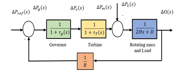
Figure 1: Isolated power system control block diagram based on LFC adapted from [12]
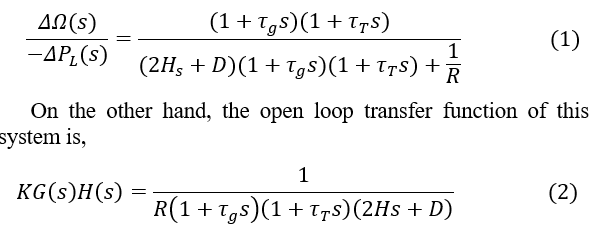
Whether the control system is in stable condition (i.e., not attacked by an unauthorized person), the system frequency falls than the normal value for a short time due to sudden load changes. The frequency sensor detects a decrease in the system’s frequency and transmits the signal to the LFC for proper speed control. The LFC prime mover adjusts the governor speed control based on the signal from the frequency sensor to compensate the speed and frequency of the system [12]. On the other hand, in case of an unauthorized access (i.e., cyber-attack) to the LFC loop, if any change to the speed regulation (R) occurs then that can create frequency fluctuation, which disrupts the system stability. The aim of LFC is to balance the actual (i.e., active) power in the power system by controlling the frequency of the system. In a system when the imbalance between load and generation occurs, it must be corrected within seconds to avoid frequency deviation. Depending on speed regulation (R), the governor adjusts generation with varying load demand, maintaining a stable frequency. Its value can be determined by applying Routh–Hurwitz array in its characteristics equation. The closed-loop transfer function of this system is,
Here, R refers to speed regulation, refers to turbine time constant, refers to governor time constant, H refers to generator inertia constant, D refers to load coefficient (1% change in frequency) f, refers to nominal frequency, refers to Change in load of the power system.
In LFC system, increasing the load demand ( ) causes a fall in generator frequency, and vice versa. The reason is that the response of the rotating mass inertia is insufficient to bring the generator frequency to the nominal value. A detailed discussion can be found in [1], whereas the block diagram of LFC system with cyber-attack point specifications shown in Figure 2.
Table 1: Parameters of Proposed LFC, AGC, and AGC-PID Power System Models, Adapted from [12]
| Symbols | Parameters | Values |
| Turbine time constant | 0.5 s | |
| Governor time constant | 0.25 s | |
| H | Generator inertia constant | 8s |
| D | Load coefficient
(1% change in frequency) |
1.16 |
| R | Speed Regulation | 0.04 |
| f | Nominal frequency | 50 Hz |
| Change in load | 0.25pu |
The parameters used in LFC system are presented in Table I. The power station is considered an isolated power station with a turbine-rated output is 200 MW at nominal frequency of 50Hz. Considering the sudden load changes 50 MW, according to the Routh-Hurwitz array to LFC loop with considering the values of parameters mentioned in Table I and Eq. 1, the obtained value of speed regulation (R) is R> 0.009678. As per theoretical calculation, it is proved that if R is equal to 0.04 then the system will be marginal stable. The frequency deviation during a cyber-attack for various R values presented in Figure 3. It is seen that the system frequency is stable for the value of R=0.04. It means that for stable operation of this power station, R should be equal to 0.04. It is clear that, depending on the affected value of R, cyber-attacks can be categorized into two ways: positively biased attack and negatively biased attack.
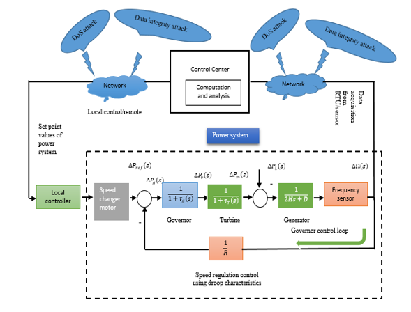
Figure 2: Attack points and general block diagram of a single-area LFC system, adapted from [1].
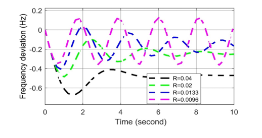
Figure 3: Frequency deviation response to different R values in LFC in case of cyber-attack.
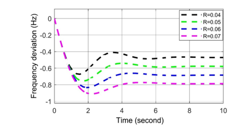
Figure 4: Frequency deviation response for positive biased cyber-attack in LFC.
- Positively biased cyber-attack on LFC
According to the result of the cyber-attack on LFC system, the value of R increases from the set value, which is called positively biased cyber-attack. It is observed from Figure 4 that the frequency oscillation curve becomes stable quickly when the value of R increases, although the frequency decreases. According to positive bias cyber-attack, the LFC loop decreases the frequency of the system, but it quickly returns to a stable position. However, an excessive deviation in system frequency is not permitted here since the governor’s excessive deviation cannot restore the system’s frequency.
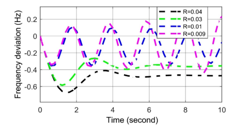
Figure 5: Frequency deviation response for negative biased cyber-attack in LFC.
- Negatively biased cyber-attack on LFC
According to the result of the cyber-attack on LFC system, the value of R decreases from the set value, which is called negatively biased cyber-attack. It is observed from Figure 5 that, the governor can restore the system frequency when R = 0.03 but it takes more time than the set value R = 0.04. In contrast, other frequency curves never reach to a steady state in both cases (i.e., R = 0.01 and R = 0.009). As a result of the cyber-attack, speed regulation value falls down the steady state position (i.e., R> 0.009678), so frequency deviation is being fluctuated in nature. It increases the oscillations since the governor cannot restore the system’s frequency. It can be said that the negative biased cyber-attack is very difficult to maintain a stable system condition, and such a cyber-attack can disrupt the whole system.
2.2 Cyber-Attack Impacts on AGC
It is known that changes in system loads at primary LFC result in fluctuations in the steady state frequency depending on the governor speed regulation [12]. It takes more time to restore the system frequency of the desired value (i.e., LFC primary loop). A change in LFC is required to mitigate the frequency fluctuation to zero. Adding an integral controller to the LFC system is referred to as an automatic generation control (AGC). The necessary controller gain (KI) improves the nature of the system in such a way that the activity finally forces the frequency fluctuation to zero [2]. The KI must be adjusted with a proper set value for a suitable transient response. Thus, it is essential to set the value of this parameter to an appropriate level for proper operation. Because of the failure to select KI, the governor cannot restore the system’s frequency. As a result of the cyber-attack, KI is considered as a vulnerable quantity. According to unauthorized access to the AGC loop, any change to KI may create frequency fluctuation, disrupting the system’s stability. Here, the severe effect of cyber-attack on automatic generation control is analyzed. The closed-loop transfer function is shown in Eq. 3, and the block diagram of a simple AGC presented in Figure 6, consisted by some parameters mentioned in Table I. The closed loop transfer function for AGC loop as,
It is known that an attacker can change the values of vulnerable parameters by increasing (positive biased cyber-attack) or decreasing (negatively biased cyber-attack) them during data manipulation [8], [13]-[14] . An attacker can operate them simultaneously or, individually. According to Equation (3) and Figure 6, the various curves for frequency deviation depending different KI values are presented in Figure7. The appropriate KI value equals to 9 for the zero frequency deviation is determined here.
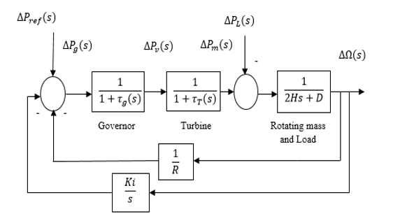
Figure 6: Isolated power system control block diagram of typical AGC
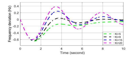
Figure 7: Frequency deviation response to different Ki values in AGC in case of cyber-attack.
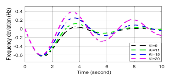
Figure 8: Frequency deviation response for positive biased cyber-attack in AGC.
- Positively biased cyber-attack on AGC
According to the result of the cyber-attack on AGC system, the value of KI increases from the set value, which is called positively biased cyber-attack. AGC system can lead to frequency deviation due to malicious data access. Hence, the frequency deviation of the system oscillated and became unstable. A positive biased cyber-attack’s impact on the AGC is presented in Figure 8. It is observed that the frequency oscillation curve can return quickly to the stable state when the set value of KI = 9. On the other hand, the frequency deviation curve oscillates slightly when KI = 11. The frequency deviation curves oscillate more than the previous ones while KI = 15 and 20, respectively. The reason is that the governor cannot restore the system’s frequency, which ultimately disrupts the system’s stability. Thus, it can be concluded that the positive biased cyber-attack severely affects the system’s frequency.
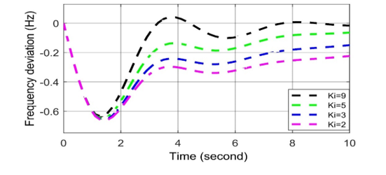
Figure 9: Frequency deviation response for negative biased cyber-attack in AGC.
- Positively biased cyber-attack on AGC
According to the result of the cyber-attack on AGC system, the value of KI increases from the set value, which is called positively biased cyber-attack. AGC system can lead to the frequency deviation due to malicious data access. Hence, the frequency deviation of the system is oscillated and become unstable. The impact of positive biased cyber-attack on the AGC presented in Figure 8. It is observed that the frequency oscillation curve can return quickly to the stable state when the set value of KI = 9. On the other hand, the frequency deviation curve oscillates slightly when KI = 11. The frequency deviation curves oscillate more than the previous ones while KI = 15 and 20, respectively. The reason is that the governor cannot restore the system’s frequency, which ultimately disrupts the system’s stability. Thus, it can be concluded that the positive biased cyber-attack severely affects the system’s frequency.
- Negative biased cyber-attack on AGC
According to the result of the cyber-attack on AGC system, the value of KI decreases from the set value, which is called negatively biased cyber-attack presented in Figure 9. It is observed that because of the negative biased attack, frequency is deviated from the set value (i.e., Ki= 9) and an unwanted delay in restoring system frequency. As a result, the negative biased attack disables the integral controller and opposes the purpose of using the KI. Negatively biased cyber-attack less serious than positively biased cyber-attack for frequency disturbance because it does not oscillate the nature of the frequency fluctuation.
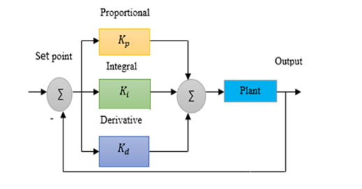
Figure 10: Block diagram of PID controller
2.3 Modelling of PID controller
In industrial applications, PID controller is the most popular approached feed-back controller. It is used to stabilize power systems, provide better frequencies, and reduce errors in the steady state. In order to evaluate the PID controller output, three different gain parameters are used in this controller, such as, the proportional gain, integral gain, and derivative gains are used [15]-[16],exhibited in Eq. (4). The conventional PID controller structure and parameter values presented in Figure 10 and Table 2.
2.3.1 Cyber-Attack Impacts on AGC-PID
The stability of the proposed typical AGC model can be updated using a PID controller for better response. The isolated power system block diagram based on AGC-PID shown in Fig 11 and the parameters used in this model mentioned in Tables I and II. It is optimistic that cyber-attacks on AGC-PID may disrupt the stability of the frequency operation. For a suitable transient response, the PID controller gain (i.e., Kp, Ki and Kd) must be adjusted with proper tuning [2], [15]-[17]. Because of the failure of selecting the proper PID controller gain, the governor is unable to restore the frequency of the system. Thus, it is important to determine the values of these parameters optimally for proper operation. That’s why, PID controller gain (i.e., Kp, Ki, and Kd) considers as the vulnerable quantity during cyber-attacks. An attacker can change the values of vulnerable parameters by increasing (i.e., positive biased cyber-attack) or, decreasing (i.e., negatively biased cyber-attack) them during data manipulation [8], [13]-[14].
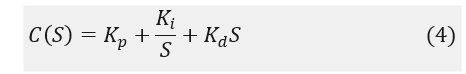
Table 2: Tuning Parameters of AGC-PID controller
| Symbols | Parameters | Values |
| Proportional gain | 90.58 | |
| Integral gain | 70.89 | |
| Derivative Gain | 57.80 |
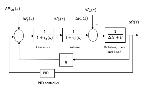
Figure 11: Block diagram of Power system control based on AGC-PID
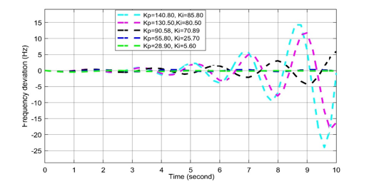
Figure 12: Frequency deviation response to different Kp and Ki values in AGC-PID in case of cyber-attack
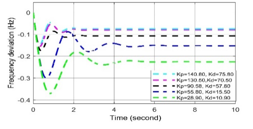
Figure 13: Frequency deviation response to different Kp and Kd values in AGC-PID in case of cyber-attack
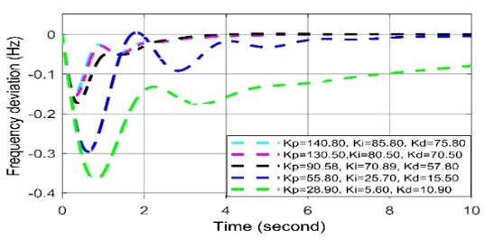
Figure 14: Frequency deviation response to different Kp, Ki and Kd (i.e., PID) values in AGC-PID in case of cyber-attack.
For positive biased cyber-attack, in Figs. (12-14), it is observed that the frequency oscillation curve can return quickly to the stable state in all cases when the set values of Kp= 90.58, Ki = 70.89, Kd = 57.80. When any two values among the three are being increased, the overshoot and settling time response increase. However, an excessive deviation in system frequency is not permitted here since the governor’s excessive deviation cannot restore the system’s frequency.
In case of negative biased cyber-attack, it is observed in Figs. (12-14) In all cases, the frequency oscillation curves are being oscillated more than the curves of set values (i.e., Kp= 90.58, Ki = 70.89, Kd = 57.80). Thus, it can be said that the negatively biased cyber-attack more serious than positively biased cyber-attack.
2.4 Cyber-Attack Impacts on AVR
The generator uses AVR as the primary means of controlling reactive power. The AVR control system considers the amplifier, exciter, generator, and sensor dynamics. The error signal is amplified and used to change the exciter terminal voltage by controlling the exciter field. The generated EMF changes by changing the current of the voltage generator at the exciter terminal. Thus, the reactive power is modified to keep the voltage stable [12]. It is known that cyber-attacks on the AVR is able to disrupt the stability of the voltage operation that may damage the conductor insulations and home appliances. Therefore, it is essential to consider the impact of a cyber-attack on AVR system in order to avoid such difficulty. The block diagram of AVR presented in Figure 15, where the amplifier gain (KA) is determined using Routh-Hurwitz array. The integrated system parameters for AVR are mentioned in Table III. The closed loop transfer function for AVR loop is as,
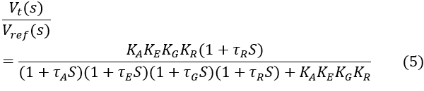
Figure 16 shows the terminal voltage disruptions during cyber-attack for various KA values. It is observed that because of the cyber-attack on AVR, any changes in KA, the voltage fluctuations are obtained that disrupt the stability of the system. It is clear that, depending on the affected value of KA, cyber-attacks can be categorized into two ways: positively biased cyber-attack (i.e., increasing KA) and negatively biased cyber-attack (i.e., decreasing KA).
Table 3: Parameters of Proposed AVR System model
| Parameters | Symbol and value | Time constant |
| Amplifier | =10 | =0.1s |
| Exciter | =1 | =0.4s |
| Generator | =1 | |
| Sensor | =1 |
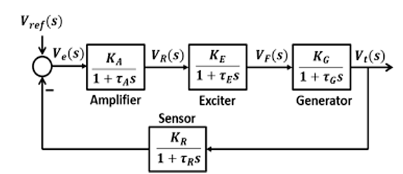
Figure 15: Power system control block diagram based on AVR, adapted from [12]
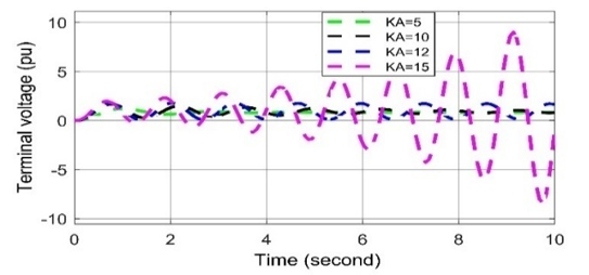
Figure 16: Voltage deviation response to different KA values in AVR in case of cyber-attack
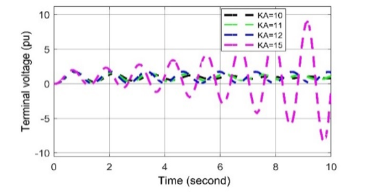
Figure 17: Voltage deviation response for positive biased cyber-attack in AVR
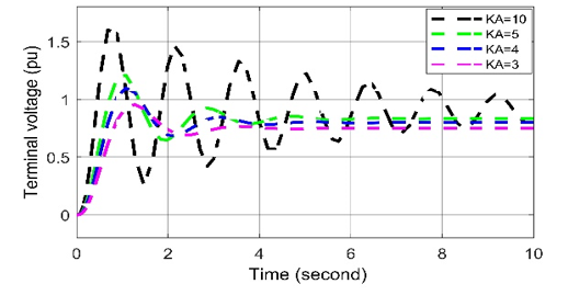
Figure 18: Voltage deviation response for negative biased cyber-attack in AVR
2.4.1 Positively biased cyber-attack on AVR
According to the result of the cyber-attack on AVR system, the value of KA increases from the set value, which is called positively biased cyber-attack. When the cyber-attack is performed on AVR, the system’s terminal voltage oscillates and becomes unstable. In the impact of positive biased cyber-attack on AVR presented in Figure 17. It is observed that the voltage fluctuation curve is oscillated in nature when the set value of KA = 10. On the other hand, voltage fluctuation curves are slightly oscillated while KA = 11 and 12, respectively. Furthermore, serious voltage fluctuation is occurred in case of KA = 15. The reason is that because of not selecting the proper values of KA, the exciter is unable to restore the voltage of the system. Thus, it can be concluded that the positive biased cyber-attack on AVR severely affects voltage disturbances as oscillating in nature.
2.4.2 Negatively biased cyber-attack on AVR
According to the result of the cyber-attack on AVR system, the value of KA decreases from the set value, which is called negatively biased cyber-attack presented in Figure 18. It is observed that because of the negative biased attack, voltage is deviated than nominal value (i.e., KA = 10) and an unwanted delay in the terminal voltage. As a result, the negative biased attack disables the amplifier gain and opposes the purpose of using the KA. Negatively biased cyber-attack less serious than positively biased cyber-attack for voltage disruptions but both are oscillate in nature.
2.5 Cyber-Attack Impacts on AVR-PID
The stability of the proposed AVR model can be updated using a PID controller for better response. The reason is that the normal AVR is suffered by two limitations: (i) availability of long-term oscillation response and (ii) larger steady-state error. PID controller has three advantages: (i) minimizing the steady-state error, (ii) decreasing the settling time, and (iii) reducing oscillation and overshoot [12]. However, during the cyber-attack on AVR-PID, for a suitable transient response, the PID controller gain (i.e., Kp, Ki and Kd) must be adjusted with proper tuning [17]-[18]. Because of the failure to select the proper PID controller gain, the exciter cannot restore the voltage of the system. Thus, it is important to determine the values of these parameters optimally for proper operation [17]. That’s why PID controller gain (i.e., Kp, Ki, and Kd) considers as a vulnerable quantity during cyber-attacks. An attacker can change the values of vulnerable parameters by increasing (i.e., positive biased cyber-attack) or, decreasing (i.e., negatively biased cyber-attack) them during data manipulation [8], [13]-[14]. Figure 19 shows the block diagram of a simple AVR-PID, where some parameters used presented in Tables II and III.
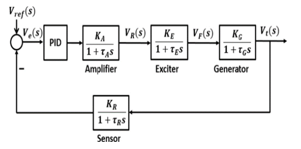
Figure 19: Power system control block diagram based on AVR-PID, adapted from [12]
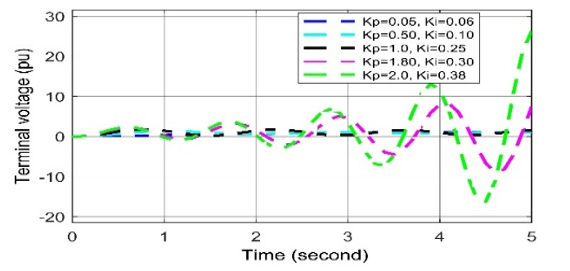
Figure 20: Voltage deviation response to different Kp and Ki values in AVR-PID in case of cyber-attack.
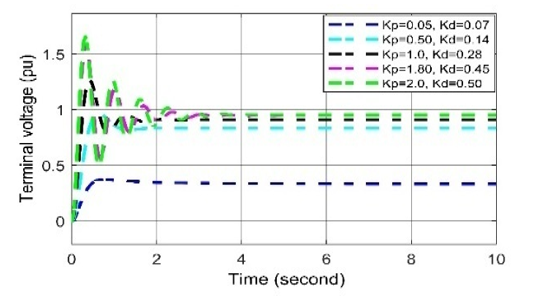
Figure 21: Voltage deviation response to different Kp and Kdvalues in AVR-PID in case of cyber-attack
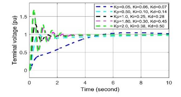
Figure 22: Voltage deviation response to different Kp, Ki and Kd values in AVR-PID in case of cyber-attack
In case of positive biased cyber-attack, in Figs. (20-22), it is observed that the voltage oscillation curve can return quickly to the stable state in all cases when the set values of Kp= 1.0, Ki = 0.25, Kd = 0.28. When any two values among the three are being increased the overshoot and settling time response increasing and in order to, an unwanted delay in restoring system voltage.
For negative biased cyber-attack, it is observed in Figs. (20-22), In all cases, the voltage oscillation curves are being oscillated more than the curves of set values (i.e., Kp= 1.0, Ki = 0.25, Kd = 0.28.), which can create voltage disturbance, which disrupts the system stability. Thus, it can be said that the negatively biased cyber-attack more serious than positively biased cyber-attack, where both forms of attacks are oscillated in nature.
3. Conclusion
The impact of cyber-attack on power systems in terms of frequency disturbances and voltage disruptions during changing loads has been investigated in this paper. In this regard, five individual controllers (i.e., LFC, AGC, AGC-PID, AVR, and AVR-PID) are introduced and incorporate two sets of system models.
In order to investigate the impact analysis properly, a series of experiments were conducted using the MATLAB-Simulink tool. The simulation results were obtained depending on the nature of the cyber-attacks shown according to the positive and negative biased cyber-attacks. It was observed that in LFC, a negative biased cyber-attack is more severe than a positive biased attack for frequency disturbance (see Figures 3-5), whereas, in AGC, a positive biased cyber-attack is more severe than a negative biased attack for frequency disturbances (see Figures 7-9). Furthermore, in AGC-PID, negative-biased cyber-attacks are more severe than positive-biased attacks for frequency disturbances (see Figures 12-14). In contrast, regarding AVR, negative-biased cyber-attack has less impact than positive-biased cyber-attack for stability in voltage disruptions, but both are oscillating in nature (see Figures. 16-18). In addition, a negative biased cyber-attack is more severe than a positive biased cyber-attack for AVR-PID, although both forms of cyber-attack oscillate in nature (see Figures 20-22).
The simulation results also confirm that, along with LFC and AGC, AVR is significant for ensuring the stability of the power system while changing the load. Finally, it can be concluded that our proposed ICAPS model is very effective in identifying the most severe attacks on the isolated power system.
In the future, we desire to achieve a reliable control system of cyber protection against unwanted access and reduce the severity of cyber-attack by considering the self-healing effectiveness process in the proposed ICAPS.
Conflict of Interest
The authors declare no conflict of interest
- M. Mohan, N. Meskin, and H. Mehrjerdi, “A comprehensive review of the cyber-attacks and cyber-security on load frequency control of power systems,” Energies, 13(15), 1–33, 2020, doi: 10.3390/en13153860.
- M. M. Uddin and M. M. Kabir, “Reduction of Frequency Disruption during Cyber-Attack in the Power System,” 2nd International Conference on Sustainable Technologies for Industry 4.0, STI, 19–20, 2020, doi: 10.1109/STI50764.2020.9350518.
- C. Chen, M. Cui, X. Wang, K. Zhang, and S. Yin, “An investigation of coordinated attack on load frequency control,” IEEE Access, 6, 30414–30423, 2018, doi: 10.1109/ACCESS.2018.2845300.
- A. Farraj, E. Hammad and D. Kundur, “On using distributed control schemes to mitigate switching attacks in smart grids,” IEEE 28th Canadian Conference on Electrical and Computer Engineering (CCECE), Halifax, Canada, 1578-1582, 2015.
- A. K. Farraj, E. M. Hammad, A. Al Daoud, and D. Kundur, “A game-theoretic control approach to mitigate cyber switching attacks in Smart Grid systems,” IEEE International Conference on Smart Grid Communications, 958-963, 2014 , doi:10.1109/SmartGridComm.2014.7007772.
- D. Kirschen and F. Bouffard, “Keep the Lights On and the Information Flowing,” IEEE Power and Energy Magazine, 7(1), 55–60, 2009, doi: 10.1109/MPE.2008.930656.
- J. Yan, C. C. Liu, and M. Govindarasu, “Cyber intrusion of wind farm SCADA system and its impact analysis,” IEEE/PES Power Systems Conference and Exposition, PSCE, 1–6, 2011, doi: 10.1109/PSCE.2011.5772593.
- S. Sridhar and M. Govindarasu, “Model-based attack detection and mitigation for automatic generation control,” IEEE Transactions on Smart Grid, 5(2), 580–591, 2014, doi: 10.1109/TSG.2014.2298195.
- M. Vrakopoulou, P. M. Esfahani, K. Margellos, J. Lygeros, and G. Andersson, “Cyber-attacks in the automatic generation control,” Power Systems,79, 303–328, 2015, doi: 10.1007/978-3-662-45928-7_11.
- A. Dagoumas, “Assessing the impact of cybersecurity attacks on power systems,” Energies, 12(4), 2019, doi: 10.3390/en12040725.
- O. I. Elgerd and C. E. Fosha, “Optimum Megawatt-Frequency Control of Multiarea Electric Energy Systems,” IEEE Transactions On Power Apparatus and Systems, 89, 556-563, 1970.
- H. Saadat, Power system analysis, Mcgraw-Hill, 1999.
- S. Biswas and A. Sarwat, “Vulnerabilities in two-area automatic generation control systems under cyberattack,” Proceedings – 2016 Resilience Week, RWS, 40–45, 2016, doi: 10.1109/RWEEK.2016.7573304.
- S. Adepu, N. K. Kandasamy, J. Zhou, and A. Mathur, “Attacks on smart grid: power supply interruption and malicious power generation,” International Journal of Information Security, 19 (2), 189–211, 2020, doi: 10.1007/s10207-019-00452-z.
- M. M. Uddin, M. K. Saifullah, and M. M. Kabir, “PID Controller Based Automatic Generation Control for Three Area Interconnected Power System,” International Conference on Information and Communication Technology for Sustainable Development, (ICICT4SD), 300–305, 2021, doi: 10.1109/ICICT4SD50815.2021.9396971.
- R. P. Borase, D. K. Maghade, S. Y. Sondkar, and S. N. Pawar, “A review of PID control, tuning methods and applications,” International Journal of Dynamics and Control, 2020, doi: 10.1007/s40435-020-00665-4.
- G. Singh and J. K. Dhami, “Load Frequency and Voltage Control of Two Area Interconnected Power,” International Journal of Engineering Research & Technology (IJERT), 8 (15), 1–4, 2016.
- M. Nagendra and M. Krishnarayalu, “PID Controller Tuning using Simulink for Multi Area Power Systems,” International Journal of Engineering Research & Technology (IJERT), 1(7), 1–9, 2012.
No related articles were found.