Frequency Oscillation Suppression of Interlinked Solar PV-Thermal Power System using HVDC Link

Adv. Sci. Technol. Eng. Syst. J. 7(5), 73–78 (2022);
 DOI: 10.25046/aj070510
This paper looks for the merging of solar PV power plant with thermal power generation and interlinked through tie-lines approaching into an interlinked PV-Thermal model for the design and analysis of load frequency controllers. Moreover, the different models of controllers are also proposed and tested to regulate the frequency of PV-Thermal interlinked system for a certain disturbance in one of the regions of an interlinked system. The choice of auxiliary controllers is assessed utilizing assorted tuning strategies and the comparative examination of all models are shown via graphical response and via calculating numerical values to bring back the frequency and tie-line power deviations back to the standard level and to analyze the viable control activity. In addition, an HVDC link is also used between linked PV-Thermal areas to stabilize the frequency and tie-power quickly as well as to stabilize the system operation for alteration in changing loading conditions of the interlinked system.
1. Introduction
Load frequency control (LFC) is a critical process in the power system, and it determines the quality energy supply to the cutting-edge society. We fulfil this requirement by matching the power system generation with the power demand and hence frequency manages to its original value i.e., 50 Hz. However, the power demand continuously changes over the complete day and hence it shifts the frequency value from 50 Hz to either up or low from the original value and therefore the power customers are affected. Subsequently, load frequency controllers are required on the generators in position to keep the power system generation up or moo as per the power demand. This gives the electrical energy to the clients with least change from the standard and acceptable level (i.e., 50Hz).
The frequency stability reflects approximately the beginning time and moment of control activity. As there’s an unbalance between the power generation and power demand, the first control action (Primary control) is initiated and tries to increase or decrease the power generation as per the requirement. The primary control loop is with the synchronous generators and known as first level of control. In any case, the action of primary control loop is limited, slow and hence unable to take the frequency of the system back to its original value and consequently the auxiliary control activities (i.e., secondary control) plays a vital part in achieving quick reclamation to power system frequency to perceived level.
Apart from this, the regions are interconnected with the means of tie-lines which generally interchange power between the regions, and these are AC tie-lines. But they suffer with large number of technical problems and one of the major issues are transferring of disturbances between the regions and that is why these drawbacks can overcome via moving the HVDC tie-line with AC tie-lines between the regions. Advance, it is continuously fitting that each region ought to meet its claim power request whereas overseeing the power give-and-take over the tie-lines to the plan value [1-2].
In any case due to continuous change in power demand as per the client’s requirement ultimately results in frequency as well as tie-line power alteration from the beginning level and hence a secondary control plan is persistently required in the system. The deviation in frequency with power deviations over tie-lines combined in a linear form is recognize as area control error (ACE). South Africa is moving ahead in orchestrate to meet its current and future power demand through cheap as well as clean sources such as sun fuelled control well known as PV based control. In any case, it is enormously troublesome to ACE deviations in the power system as the power generated through PV is exceedingly convulsive in nature.
Still, the PV based power generation is conclusion of the country considering its boundless openness, brought compelling and defilement free keeping the environment of the country clean and sickness free as well as in arrange to cater the current as well as rising power demands of South Africa. An introductory exertion in frequency management reflects about is to investigate the controller plan based on classical approach [3-4].
In any case, this approach appears to be totally unsuccessful in view of set working conditions of the power system. The controller plan approach for frequency regulation have progressed over the past few years. Assorted calculations such as optimal control by seeing each state [5]; output vector feedback design seeing crucial states [6], changing structure [7] and robust controller designs [8-9] are well attempted over the last number of years to reach the LFC benchmarks. Be that as it may, most of the frequency steadiness remedies are given for well establish plants i.e. thermal power or for combination of hydro-thermal and exceptionally scarce approaches [10-13] were available for solar PV generation and integration to the existing systems. The solar PV can generate power in one of the regions and can be interlinked to thermal power via tie-lines in order to have stable operation. Further an HVDC link may prove to be more efficient in meeting the standards of solar PV-Thermal as well as to deliver quality energy to people of South Africa.
It is well-known that the managers and labour working in assorted control businesses are very comfortable with the different structures of auxiliary controller which are “PI (proportional-integral), PD (proportional-derivative), proportional-integral-derivative (PID)” to oversee industry operations in day-to-day life in different spaces as the operation of these controllers and setting the pickup values are much easier for them and these can be achieved by considering the graphical system response [14] and hardly required any numerical calculations. Although, the pickup values and the controller design play a challenging role in achieving the required control target and sometimes it is also advisable to design and check the diverse controller designs for a certain application [15]. Within the scope, this paper is set to;
- Present mathematical model of PV and thermal power interlinked through tie-line i.e., PV-Thermal. To discuss the transfer function model of HVDC link.
- Create the conventional validation of solar PV in region one with thermal power in region two and these two power generated regions are connected via help of HVDC link parallel to AC tie-lines.
- Further, to propose and to calculate the pick-up value of various auxiliary controllers for LFC using various tuning methods and to see the merits of one over other design for step disturbance.
- The outcomes are shown via graphs for various states to find the best design for the proposed LFC.
- At last, the performance of auxiliary controllers are also matched by calculating the error (integral time multiplied by absolute error) for all LFCs with and without HVDC link to show the positive benefits of using HVDC running parallel to tie-lines.
2. Details of PV-Thermal LFC Model
The PV cell is made up of current source and it is directly related to solar radiation with one diode parallel to it. It also has a small resistance in series and its schematic representation is shown in Figure 1 [10-13]. Further the output of this cell depends on solar radiation and surface temperature. Generally, the MPPT technique is used to achieve the maximum output from PV and hence it enhances the output as well as efficiency of PV.
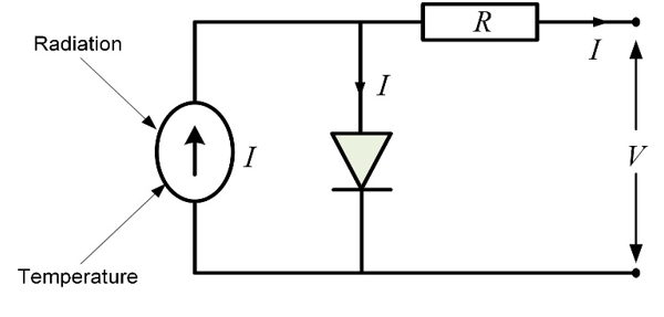
Figure 1: Representation of PV cell
The model of PV is a combination of PV panel, an inverter to convert DC power to AC power, MPPT system and filter. The complete representation in form of transfer function (TF) is as follows [10-13]:
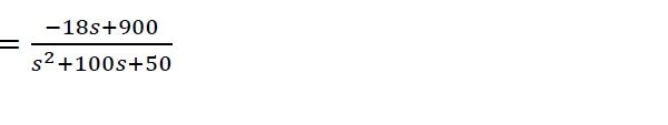 (1)
(1)
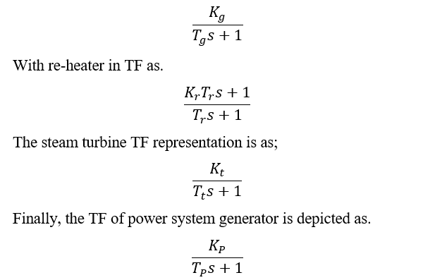
The present work is the interconnection of PV with thermal power finally coming into an PV-Thermal model for frequency regulation of the power system. The TF of PV is given in equation (1) and can be used for load frequency control studies. The thermal power system includes governor to regulate the flow of steam and its output is connected to turbine with finally the shaft of turbine coupled to the power system generator. The PV-Thermal areas are interlinked via AC tie-line. The governor for thermal area in
The interlinked PV-Thermal model for LFC is shown in Figure 2 and these areas are interlinked via AC tie-line.
However, these tie-line struggle to damp out the system oscillations quickly as well as disturbances are transferred from one area to another and hence affect the customers. These problems can be solved by running HVDC link parallel to AC.
The HVDC interface comprises of a rectifier and an inverter. The terminating points are balanced to control the rectifier and the inverter. The first-order exchange work of dc-link is communicated as:
![]() (2)
(2)
Where, KDC is the gain of the link as well as TDC represent the responding time of HVDC link.
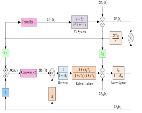
Figure 2: PV-Thermal LFC model
3. Design of Auxiliary Controllers for PV-Thermal System
One of the most common auxiliary controllers used in different types of power as well as in control industries is PID as it has three diverse control abilities which are “proportional, integral & derivative” and these abilities help the system response to come back to initial value quickly after certain disturbance. The PID work on the concept of feedback system; as PID is connected in feedback and hence it calculates the difference between actual and desired value i.e., error and tries to minimize the error by regulating the input of the system. In present research work, the aim of connecting the PID is to increase or decrease the electrical power in solar PV as well as in thermal power plants as per the requirement of electrical power and hence to attain the balance between the two so that frequency of each area and connecting tie-lines deviations should be minimized. As PID has three diverse control abilities and that is why pickup values of each control need to be calculated correctly. At first, the disturbance of value 0.01 per unit (p.u.). is imposed in area one of an interlinked PV-Thermal and at the same time, the pickup value of proportional control needs to be increased in small steps until the system start showing complete oscillations as per the Ziegler–Nichols (ZN) practice [15].
The pickup after which the system loses its stability is known as extreme pick up (Ku) for thermal region and the time between crests (Tu) is well-known in order to calculate the picks up of PID for different modes.
The same formulation is additionally taken after for PV system also. At last, with the assistance of ZN practice the pick-ups of different modes of PID are calculated and given in Table 1 for solar PV region and Table 2 for thermal system and calculated value of error i.e., ITAE is shown in Table 3 with and without inclusion of HVDC link.
Table 1: PID Gains for solar PV system
| Auxiliary Controller | Kp (Proportional Gain) | Ki
(Integral Gain) |
Kd
(Derivative Gain) |
| Proportional Integral (PI) | 1.79 | 1.542 | |
| Proportional Derivative (PD) | 3.19 | 0.559 | |
| Classic PID | 2.39 | 3.428 | 0.419 |
| Pessen Integral Rule | 2.80 | 5.000 | 0.588 |
| Some Overshoot | 1.30 | 1.902 | 0.622 |
| No Overshoot | 0.80 | 1.15 | 0.373 |
Table 2: PID Gains for thermal power
| Auxiliary Controller | Kp (Proportional Gain) | Ki
(Integral Gain) |
Kd
(Derivative Gain) |
| PI | 1.79 | 2.4 | |
| PD | 3.19 | 0.36 | |
| Classic PID | 2.39 | 5.33 | 0.27 |
| Pessen Integral Rule | 2.80 | 7.77 | 0.37 |
| Some Overshoot | 1.33 | 2.96 | 0.40 |
| No Overshoot | 0.80 | 1.77 | 0.24 |
Table 3: ITAE values with and without HVDC Link
| Auxiliary Controller | ITAE | ITAE with HVDC |
| PI | 4.224 | 0.05129 |
| PD | 0.116 | 0.116 |
| Classic PID | 0.0065 | 0.00104 |
| Pessen Integral Rule | 0.0058 | 0.00099 |
| Some Overshoot | 0.0202 | 0.01547 |
| No Overshoot | 0.0565 | 0.02095 |
4. Simulation Details and Analysis for LFC
The research work is aimed to check the feasibility of generating electrical energy via means of renewable solar PV in one area and interlinking to power generation via means of thermal power in another area and connected through tie-lines resulting into an interlinked PV-Thermal system used for designing and analysis of load frequency controllers to regulated frequency and interlinked tie-lines deviations for a certain disturbance.
In addition, the PV-thermal areas are connected via additional HVDC tie-line running parallel to AC tie-line between two interlinked areas. The HVDC tie-lines parallel to AC have the capability to improve the load frequency control responses due to lesser time constant and will show reduce oscillations, better settling time and steady state error to zero value.
The various sub-designs of PID such as “PI, PD & PID” are design and tested for interlinked model to check the superiority of one design over other design. The auxiliary controllers are design to minimize frequency and tie-power deviations to minimum or zero value.
The Zeigler-Nichols tuning method is used to move forward the framework reactions. The picks up of different modes of controllers are assessed with the assistance of ZN practice. The obtained pickup values for various PIDs are given in Table 1 for solar PV and for thermal plants in Table 2. The diverse calculated error values for each mode of auxiliary controllers are given in Table 3. The Table 3 also shows the ITAE with and without inclusion of HVDC link. Now the integral time absolute error (ITAE) definition is chosen to obtain the output of various modes of auxiliary controllers and ITAE is built on the basis of ACE.
The step load is applied in thermal power and PV-Thermal responses for various modes are obtained by considering HVDC parallel to AC tie-line between PV-Thermal regions. The execution of interconnected PV-Thermal is assessed on gotten picks up as given in Table 1 & Table 2 for different strategies and the comparative comes about for frequency, AC tie-power alteration & ACE of each area is appeared in Figures 3-7.
A look at these outcomes about clearly appears that PD mode is unable to take the system results back to reference value within 50 seconds also. The calculated ITAE is 0.116 and it is highest in the group of these control actions.
The results secure through PI and No Overshoot have the supported motions for frequency, AC tie-line power and ACEs for area 1 & 2 which is additionally not alluring seeing the required control and ITAE is 4.224 for PI without HVDC link and it reduces to 0.05129 with HVDC.
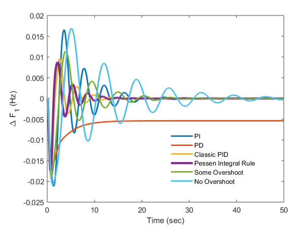
Figure 3: Graphical outcomes of PV-Thermal system
At the same time the ITAE for No Overshoot is 0.0565 without HVDC link & it reduces additionally with HVDC. The results about advertised by Some Overshoot strategy are superior to PI, PD & No Overshoot nevertheless having number of oscillations and settling time is as large as of 20 seconds for all outcomes. The results obtained via classic PID is much better for all graphical results in view of reduced overshoot, lesser oscillations and much lesser time to reach the steady state value when matched with regards to that obtained through other studied auxiliary load frequency controllers.
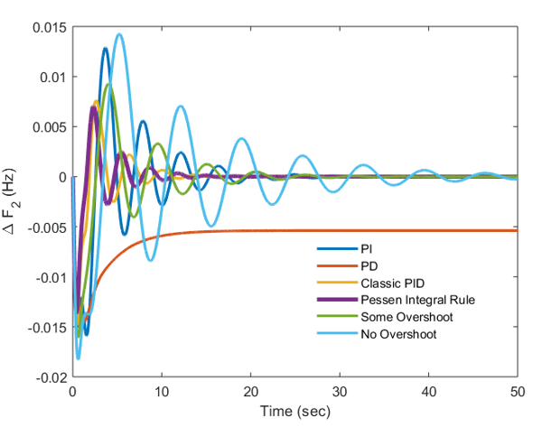
Figure 4: Graphical outcomes of PV-Thermal system
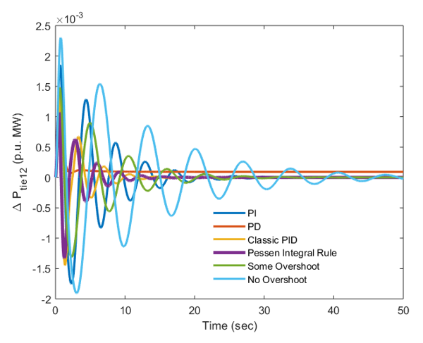
Figure 5: Graphical outcomes of PV-Thermal system
The frequency responses by using the Pessen Integral Rule have (-0.02) Hz of variation from the original value for solar PV area with response settling in 14 seconds. At the same time, the frequency variation is (-0.015) Hz for thermal power plants with settling in 10 seconds & able to go back to the reference or original value much faster than solar PV plants. The same trend is seen for response of tie-line power, ACEs for area 1 and 2 and hence it is concluded that Pessen Integral Rule based auxiliary controller shows much better output in reaching the targets of PV-Thermal system in least conceivable time.
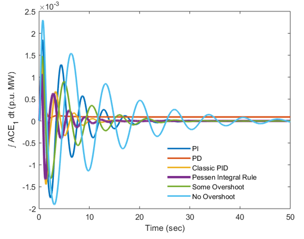
Figure 6: Graphical outcomes of PV-Thermal system
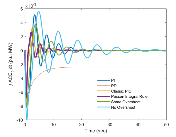
Figure 7: Graphical outcomes of PV-Thermal system
The obtained ITAE is 0.0058 and it comes out to be 0.00099 and this value of ITAE is least ITAE in complete group of investigated auxiliary controllers. It is additionally seen that the settling time and top of overshoot is also less for responses of area-2 when matched with area-1. The reason is that thermal power are well establishing in terms of design and development over the last number of years where as solar PV plants depend highly on solar radiation for generating the output and the solar radiation is highly intermittent in the nature. Further, it is also noted that HVDC link has minimized the ITAE of all auxiliary controllers. When ITAE of various modes are compared and all ITAE values are obtained with respect to HVDC running similar to AC between PV-Thermal regions, it is further verified that ITAE of Pessen Integral Rule outperform all other modes and reach to best possible minimum limit and hence justify the positive impact of this mode for PV-Thermal System.
5. Conclusions
This paper attempts to achieve the of linking of Solar PV power plants with the help of tie-lines to thermal power coming into an interlinked system. In addition, an impact of HVDC link with AC tie-line is also investigated in this work. The distinctive modes of PID are outlined by developing and checking various PID structures. The design and investigations of various load frequency controllers revealed that the design accomplished by Pessen Integral Rule is quick enough to bring back the responses of PV-Thermal system such as (frequency of area-1 and 2, tie-line power and ACEs of area-1 and 2) deviations to original value after the load disturbance. The output of all responses is smooth with very few oscillations and coming back to original value much faster in comparison to other load frequency controllers. It is also perceiving that error value i.e., ITAE obtain via Pessen method is not as much of when compared with ITAE of other PID controllers. The significant reduction in error values is observed for all auxiliary controllers with inclusion of HVDC link. With HVDC link also, ITAE achieved via Pessen Integral Rule is minimum when compared with other auxiliary controllers and hence this method of PID outperforms over other auxiliary controllers for present studies. However, the research work can be extended to calculate the values of various PIDs by using optimization techniques. The effect of non-linearity and time delay with sensitivity analysis also need to be study for PV-Thermal system. The work may be extended to deregulated environment in view of various market transactions and to study the ancillary services such as LFC in deregulated environment.
Conflict of Interest
The authors declare no conflict of interest.
- E. Çelik, N. Ozturk, and E. H. Houssein, “Influence of energy storage device on load frequency control of an interconnected dual-area thermal and solar photovoltaic power system,” Neural Computing and Applications, 1-17, 2022, doi: 10.1007/s00521-022-07558-x.
- F. T. Tomy, R. Prakash, “Load frequency control of a two-area hybrid system consisting of a grid connected PV system and thermal generator,” Int J Res Eng Technol., 3(7), 573–580, 2014.
- J. Nanda, S. Mishra, and L. C. Saikia, “Maiden application of bacterial foraging based optimization technique in multi-area automatic generation control,” IEEE Trans. Power Syst., 24, 602-609, 2009, doi: 10.1109/TPWRS.2009.2016588.
- Ibraheem, P. Kumar, and D. P. Kothari, “Recent philosophies of automatic generation control strategies in power systems,” IEEE Trans. Power Syst., 20(1), 346–357, 2005, doi: 10.1109/TPWRS.2004.840438.
- Ibraheem, K. R. Niazi, and G. Sharma, “Study on dynamic participation of wind turbines in AGC of power system,” Electric Power Comp. and Syst., 43(1), 44-55, 2014, doi: 10.1080/15325008.2014.963266.
- G. Sharma, Ibraheem, and K. R. Niazi, “Optimal AGC of asynchronous power systems using output feedback control strategy with dynamic participation of wind turbines,” Electric Power Component and Systems, 43(4), 384-398, 2015, doi: 10.1080/15325008.2014.949916.
- N. N. Bengiamin, and W. C. Chan, “Variable structure control of electric power generation,” IEEE Trans Power Apparatus Syst., PAS-101, 376–380, 1982, doi: 10.1109/TPAS.1982.317117.
- G. Sharma, I. Nasiruddin, K. R. Niazi, and R. C. Bansal, “Robust automatic generation control regulators for a two-area power system interconnected via AC/DC tie-lines considering new structures of matrix Q”, IET-Generation Transmission and Distribution, 10(14), 3570-3579, 2016, doi: 10.1049/iet-gtd.2016.0321.
- Y. Wang, R. Zhou, and C. Wen, “Robust load-frequency controller design for power system”, IEE Proc. C, 140(1), 11-16, 1993, doi: 10.1049/ip-c.1993.0003.
- E. S. Ali, “Speed control of DC series motor supplied by photovoltaic system via firefly algorithm,” Neural Comput Appl., 26(6), 1321–1332, 2015, doi: 10.1007/s00521-014-1796-5.
- A. S. Oshaba, E. S. Ali, and S. M. Abd-Elazim, “PI controller design for MPPT of photovoltaic system supplied SRM via BAT search algorithm,” Neural Comput Appl., 28(4), 651-667, 2015, doi: 10.1007/s00521-015-2091-9.
- A. S. Oshaba, E. S. Ali, and S. M. Abd-Elazim, “Speed control of SRM supplied by photovoltaic system via ant colony optimization algorithm,” Neural Comput Appl., 28(2), 365-374, 2015, doi: 10.1007/s00521-015-2068-8.
- S. M. Abd-Elazim, and E. S. Ali, “Load frequency controller design of a two-area system composing of PV grid and thermal generator via firefly algorithm,” Neural Comput Appl., 1-10, 2016, doi: 10.1007/s00521-016-2668-y.
- A. Panwar, G. Sharma, I. Nasiruddin, and R. C. Bansal, “Frequency stabilization of hydro–hydropower system using hybrid bacteria foraging PSO with UPFC and HAE,” Electric Power Systems Res., 161, 74-85, 2018, doi: 10.1016/j.epsr.2018.03.027.
- J. G. Ziegler, and N. B. Nichols, “Optimum setting for automatic controllers,” Trans. ASME, 64, 759–768, 1942.
No related articles were found.