Advantages of 3D Technology in Stereometry Training

Adv. Sci. Technol. Eng. Syst. J. 7(6), 39–48 (2022);
 DOI: 10.25046/aj070605
This paper presents a new software for stereometry training. Its name is StereoMV (Stereo Math Vision). It is results from a dissertation work on the topic “Stereoscopic Training System”. It introduces virtual reality systems that are both immersive and non-immersive. The difference between them is in the equipment and the stereo effect they offer. A comparative analysis is performed between the virtual environments that are part of the software. 3D visualization is of four types: traditional, 3D active, 3D passive, and through immersive systems such as CAVE (Cave Automatic Virtual Environment) and HMD (Head Mounted Display). There are also four visualization modes in Java3D. Mixed Immediate Mode is used to implement stereoscopic projection using 3D active technology. Passive technology uses anaglyph glasses with a red and blue filter. Traditional visualization can be implemented from any computer. The system’s most important function is exporting the objects in a file with the extension .obj. All this is thanks to a Java 3D library and a new boundary method involved in generating geometric objects, which sets the program apart from existing software solutions for training in the discipline of stereometry. The software can be used for stereo visualization of random 3D models from various scientific fields. Unlike planimetry in stereometry, a three-dimensional drawing would be much more difficult to understand, and that’s why 3D technology comes to the rescue. This way, the student’s interest will be strengthened, from where their spatial thinking will be further developed.
1. Introduction
“This paper is an extension of work originally presented in conference 2021 International Conference Automatics and informatics [1]”.
One of the fastest-growing areas of the modern world is 3D technology, which in recent decades has found application in almost all spheres of society, including education. What until recently looked like science fiction is a reality today. The principle of 3D visual stereo is based on binocular parallax. One of the most important features of 3D technology is making the invisible/visible and the inaccessible/accessible. By means of it, new concepts are learned and higher levels of concentration are showed. The introduction of 3D systems in the education of the Republic of Bulgaria is currently hindered by many objective reasons, such as the lack of high-tech infrastructures and standards, as well as the insufficient awareness of potential consumers about the benefits of the new technology. These limitations can be overcome in the near future. Despite the constraints, experts predict the active introduction of 3D systems in secondary and higher education, and the first steps in this direction have been taken. The use of these systems in education will lead to a paradigm shift in how people view school and university education [2]. The application of this technological innovation in the education sector will improve how pupils and students will acquire new knowledge [3]. Three-dimensional modeling and animation of information will provide teachers with high-quality teaching materials and programs that will help students more easily absorb understand the material studied, increase their motivation and ability to learn large amounts of information.
Nowadays, solid knowledge is built faster through the so-called digital model, which can be realized through information technology and virtual reality devices [4] . The teacher’s choice of appropriate software can become a potent tool in the learning process. In this way, students will be involved in the most innovative way possible to build knowledge. The proposed new software can participate in stereometry training. In contrast to planimetry, a problem arises related to understanding three-dimensional drawing. A large part of the students does not have well-developed spatial thinking. This problem can be solved by using appropriate 3D technology, such as (virtual, augmented, mixed reality, and 3D printing). It is assumed that the greater the immersion in virtual reality, the greater the interest in mathematics on the part of students.
The article aims are to present new software for teaching geometry in three-dimensional space. It is intended for middle and upper middle schools. Virtual environments that can visualize the software are both immersive and non-immersive. The system can export the shapes to a .obj file.
2. 3D stereoscopic systems
Stereoscopic systems in a virtual environment are available with and without immersion. Each of them has specific characteristics that distinguish them from the others. Some systems require more money to invest in hardware but at the same time offer a very great experience. These are immersive systems such as CAVE and HMD. Non-immersive systems are desktop computers and can be 3D passive or active technology [5]. In one case, the active virtual environment is presented on a special stereo display, and 3D active (shooter) glasses are required. With passive technology, only a pair of anaglyph glasses is needed. Compared to other environments for VR, immersion is relatively less, but still, good experiences are offered. Their advantage is that they are relatively cheaper. And therefore, they are widely used. That is why they are suitable for application in education in the case of training in streometry.
3. Softwares for training in stereometry
After a study in European and Bulgarian education regarding the use of dynamic software in mathematics classes, it was found that the following programs have been used so far: Geogebra, Dalest, and Cabri3D. Thanks to these software solutions, students become engrossed in the presentation and study of mathematics material. The programs help the student to develop his spatial imagination and logical thinking and to accumulate new knowledge and skills. GeoGebra is an interactive program designed to learn and teach algebra, geometry, and statistics from elementary school to university. The program can work in many modes, such as a mode for 2D graphics i.e. planimetry, and a way for 3D graphics – stereometry, at the same time, there is also a mode for algebraic calculations related to the mentioned sections of geometry. The DALEST software project results from the joint work of five European universities: Cyprus, Great Britain, Portugal, Greece, and Bulgaria. The project aims to create dynamic 3D software for young people learning stereometry in middle school for young students. The CABRI 3D software system allows the construction of geometric figures in three-dimensional space and manipulations with them. The main functions of CABRI 3D and GEOGEBRA are constructing lines, surfaces, and 3D figures; translation, inversion, rotation, sections; polyhedra constructions, etc. Of the three considered software for training in the discipline of stereometry, only one of them has the possibility of implementing stereoscopy through anaglyph projection through passive 3D technology, and that is the GEOGEBRA program. The softwares uses trigonometry and the extrusion technique to construct geometric figures (polygons, prisms and pyramids) and rotational bodies. CABRI 3D and GEOGEBRA use an advanced traditional method, which is again based on trigonometry, to construct the geometric objects. An essential part of programming is regular polygons. On their basis, the complex polyhedra as prism and pyramid are constructed. As is well known, they are the basis of the geometry discipline in secondary school. The traditional way of creating them is based on trigonometry (sine, cosine, and radius). Several vertices and radius characterize them. This paper presents a new method for generating a regular polygon. It defines them by the number of vertices and the length of the side. The traditional way to create a polyhedra is by extruding a polygon defined by a radius. Here, extruding is the most used technique in 3D programming, and it is not appropriate to use when constructing geometric figures studied in mathematics. In this way, meaningful information about the vertices of the geometric body is lost. Therefore, thanks to the new method, the geometric objects are mathematically more accurate since they do not use the mentioned technique.
4. Extrude/sweep 2D graphics
One of the main techniques in 3D programming to create 3D models is extruding 2D and 3D graphics. Various arbitrary objects can be formed with it. It is usually applied to curves and polygons. The idea is that through a certain movement, such as (rotation, translation, and trajectory defined by an arbitrary curve) a complex geometric construction can be generated. Math software uses this technique in developing stereometric figures. A regular hexagonal prism generated by the traditional method is shown in Figure №1. The base is a polygon with 6 vertices and a radius equal to 2. The volume body is created by planar sectioning and setting a rule in the case of prism extrusion by translation. The diagram Figure №2 shows how the stereo system visualizes a regular polygon with new method without extrusion. First, it is necessary to enter input data, such as the number of vertices and side lengths. Here, the side length parameter is the same for each polygon. The values of parameter I vary between (3, 4, 5 and 6). Each shape is drawn using coordinate arrays. The values of the vertices are of type double. They were followed by visualization of the figure and calculating the perimeter and face.
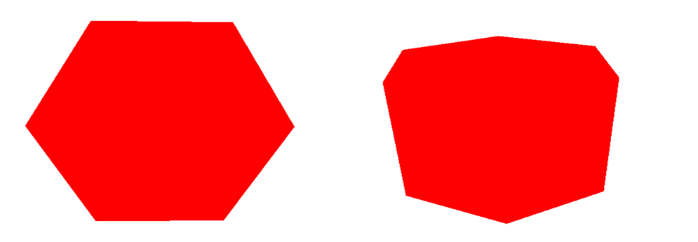
Figure 1: Traditional method and prism
5. Methods for stereoscopic visualization
The principle of 3D visual stereo is based on binocular parallax. The two images with parallax information are used, each of the images being seen by the corresponding eye, resulting in different incarnations. There are two methods to distinguish it [6]: First one with the help of display, and second one with stereo glasses.
6. 3D stereoscopic Display
3D stereoscopic displays are classified into two categories depending on the equipment:
- Autostereoscopic, which does not require additional equipment to generate a 3D stereo image.
- Stereoscopic displays: These are assisted by other devices.
In stereoscopic displays, the 3D image is obtained from two different images for the left and right eyes, respectively [7]. The two images are similar, with a slight offset from each other. The beginning was given in the 20s of the last century, mainly in films, cinema halls, and television. Nowadays this technology already has a mass application, for example: in education and video games. Stereoscopic 3D technologies are divided into active (LC liquid crystal) and passive (anaglyph and polarizing). Anaglyph technology uses two color-filtered images and relatively inexpensive glasses. The colors that are commonly used are: red-cyan, red-green and blue-red. With this system, no additional equipment is needed. It is enough to have a pair of anaglyph glasses. The main disadvantage of anaglyph glasses is that a lot of colors can be lost. The active (shooter) system is a 3D stereoscopic technique that sends the left image to the left eye and the right image to the right eye, respectively [7]. One of the most used immersive 3D systems is the HMD (Head Mounted Display) virtual helmet [7]. This is a device that is mounted on head, with a small optical display in front of each eye. The virtual helmet is used in various virtual and augmented reality applications. It is easy to operate and can be installed on any platform. This system consists of two optical parts: an input and an output pair [7]. The first pair magnifies the image on the microdisplay, while the outer pair projects the color image to the viewer. II (integral imaging display) This type of display offers 3D imaging without needing additional glasses or tracking devices. In recent years II has attracted much attention from many researchers due to its full color moving 3D imaging full parallax, which sets II apart from other 3D display technologies [7]. Volumetric display is used and developed to present 3D volumetric or animated images in space. This technology is mostly used in military, medical, and academic applications.
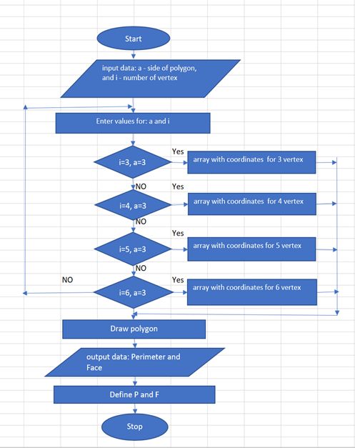
Figure 2. Diagram of polygons: new method
7. 3D Technology
The stereoscopic vision techniques that are part of the proposed new software are: HMD, active glasses, passive glasses (anaglyph) and CAVE (Cave Automatic Virtual Environment). There are several options for visual stereo. The first one uses the so-called active glasses, which alternate between the eyes in sync with the monitor. Stereoscopic perception requires each eye to receive a separate view of the scene. The view should be at a different angle and by according to the position of the head. The distance between the eyes is called interocular distance. The second way to generate stereoscopic objects on stage is by having two serial and different monitors [8]. This is precisely the way the HMD is ready to work, as each eye has its monitor. Here again, each eye has a different view, but there is no switching between the eyes and the two monitors are constantly on [8]. The display with which the three-dimensional perception is visualized is of two types: head-mounted or room mounted [8, 9]]. Most displays are single screens without head tracking. Such systems are the simplest forms of room-mounted displays. In the case of the HMD, the screens are attached to the head (i.e. when the head moves, the screens follow it). There are several options for visual stereo. The first uses the so-called Head tracking that allows head movement instead of the standard mouse, joystick, keys, and other controllers.
7.1. HMD vs Screen
The full view specification can be divided into two parts, namely the view position and the view volume [8, 9]. Here it is necessary to calculate two matrices depending on the specification. When using the HMD, the camera needs to depend on the movement of the head, so that when the user’s head moves and rotates, the 3D view moves together with it. It is important that the relationship between the eyes and the screen don’t mustn’t change. Therefore, the projection matrix remains constant [9]. When using room-mounted, the movement of the head changes the projection matrix but does not control the camera. This is a problem when watching stereo. With room mounted it is not necessary to use head tracking unless we are in stereo mode. Appearance settings depend on the location and orientation of the eyes. If the user’s head changes position, the view also changes [9]. Dynamically recalculating the projection matrix and the view matrix is a very annoying task. Java allows tracking and supports features for automatic head tracking [8]. Where the view is considered a camera. A projection matrix represents the section definition. A visual matrix represents the position of the view. The first of the matrices are defined in the coordinate system, where the eye is located at the beginning of the view to the negative direction of the application z-axis (applicate) and up to the ordinate. On the other hand, in the view/camera, the eye is located at the beginning, looking down at z and up at y.
7.2. 3D Active, Passive and Immersion Systems
Anaglyph technology does not require expensive equipment, unlike 3D active technology. Here the user must be equipped with only one pair of glasses. The colors most often used are red for the left eye and blue for the right [10]. This projection is most often used when viewing magazine photos. The idea is to filter the eye images based on color. The second technique requires two monitors for each eye to generate a stereo image. Here, as in the first technique, each eye must receive a certain image. The virtual reality helmet – HMD – works on such a principle. The difference between the two techniques is user interaction. How interactivity is carried out through the helmet is similar to non-immersive systems: through a mouse, joystick, keyboard, etc. The main feature that differs between the two systems when interacting is “Head Tracking” – a 6DoF device (six degrees of freedom) that offers 3D information in the form of location and orientation. In this way, a higher-level interaction is performed, offering a relatively more significant emotional effect on the part of the average user. The stereometry software proposed in this article can be implemented by immersive and non-immersive virtual reality devices, such as 3D active (shooter technology), 3D passive (anaglyph), and immersive systems (CAVE, HMD). With active technology, frames are alternated sequentially, first for one eye and then for the other [11]. The frequency of these frames is usually 120 Hz, 60 Hz per eye [11]. For the structure to be perceived by the viewer, special active glasses are used, which darken the glass of the eye which doesn’t have to see the frame that was displayed. Here, darkening alternate first in one eye and then in the other. The use of a synchronization device is also required. One of the systems that offer the most excellent immersive effect is the CAVE system. In this 3D technology, the projectors are placed between the walls of a cube-shaped room. As with the active technique, the user must use glasses[5, 12].
8. Java stereoscopic mode
In Java3D, rendering modes are four in number Table 1, and choosing a particular mode becomes very easy [9]. It is recommended that the programmer sticks to the first two modes.
8.1. Retained mode
This is the default rendering mode. The application remains in a continuous rendering state in this mode unless the method Canvas3D.stopRender of Java3D API (Application Programming Interface) is called. Also, in this mode, Java3D rendering will build a structure for handling geometry and operations related to 3D transformations[9].
8.2. Compiled Retained mode
Bitwise assignment in Java is one of the most confusing operations [9]. The following can be given as an example:
TransformGroup tg = new TransformGroup(); tg.setCapability(TransformGroup.ALLOW_TRANSFORM_WRITE); It should also be noted that there is a reference relationship between the classes: TransformGroup and Switch. These two classes can only be used in the first two modes and partially in the fourth mode. This is one of the main differences, which is not unimportant. The second mode gives Java the freedom to perform many optimisations. The most important of which are scene graphics compression and geometry grouping. This mode requires calling the compile() method of BranchGroup; this method optimizes the graph itself by grouping and sorting [9]. Another significant difference between the two modes is grouping, which is an advantage when there are many figures on the scene.
8.3. Immediate mode
Immediate mode – in this mode, applications intended for users have more freedom, which is at the expense of performance. This mode provides great flexibility, however rendering is at the lowest level when using it. A programmer using this mode only wants to take advantage of the geometry classes[9]. The first two modes (compression of geometry, grouping of geometry, and scene graph are more highly developed than the third.
8.4. Mixed mode
The fourth mode allows mixing the first two with the third mode. The mixed mode preserves the continuous rendering from the first two modes. For realization of the system is used this mode.
9. 3D printing and .OBJ file
3D printing, also known as additive manufacturing, creates three-dimensional solid objects corresponding to a given digital file. In this process, the object is created through successive layers of material until the 3D model itself is generated [13]. Each layer is a thinly sliced horizontal section of the object [13]. Before getting to the actual printing of the three-dimensional shape, it is necessary to go through the following steps.
- Virtual design of the object, through a 3D modeling program (for a new object), through a 3D scanner (when an existing object needs to be copied) or, in this case, through the stereoscopic system.
- The next step is to export to a .obj file
- In the end, add to the printing device.
Table 1: Java 3D stereo Mode
|
Render stereo mode |
Canvas3D |
Stereo type |
|
Retaind mode |
Canvas3D |
Active3D |
|
Compiled – retained mode |
Canvas3D BranchGroup.compile() |
Active3D |
|
Immediate mode |
Canvas3D.stopRenderer() |
hybrid |
|
Mixed Immediate mode |
User Canvas3D: preRender(), postRender(), postSwap() and renderField() |
Active3D |
Today, digitizing a real object into a 3D model becomes as easy as, for example, taking a photo. To prepare the .obj file for printing, the software slices the final model into hundreds of horizontal layers [13]. Next is uploading the 3D file to the printer; the object is created layer by layer [13]. The device makes the object by blending the layer. There are different types of technologies for working with 3D printing. One of the most used formats for storing polygon mesh information is the .obj format. One file can store data about indexed walls, normal vectors, and texture coordinates. The required data is stored in text format and can be edited using a text editor, for example, Notepad. Each line contains the following characters: • “v” – vertices • “vn” – normal vector • “vt” – for texture • “f” – for the faces. Next comes the setting of specific values. Each of the sides is formed based on a triangle and a quadrilateral as shown on Figure 6 and Figure 7 . The row data for each wall contains a description of the vertices that make up the wall by specifying the vertices. Depending on the primitive being used.
10. Results
The software presented in this article, named StereoMV runs under Windows operating system. The object-oriented programming language Java, and more specifically, the Java3D library, was chosen as the means of implementation. The software interface uses JDK (Java Development Kit) version No. 8. This article presents 3D technologies that can be involved in teaching the discipline of stereometry, which is a branch of geometry in three-dimensional space. Besides the fact that technologies are divided into systems with and without immersion, they can be divided into two more groups: room-mounted and head-mounted. The main parameters of the stereoscopic system are:
- Software functionality
Two types of geometric figures are studied in the study of stereometry in secondary school:
- Ribbed geometric figures – polygon, prism, cube, parallelepiped, and pyramid
- Rotational bodies – cone, sphere, torus, and cylinder
The stereoscopic system can generate both types of geometric objects using the new boundary method for the first objects. For rotary bodies, the traditional extrusion method is used translational (cone and cylinder) and rotational (sphere and torus). The new program enables objects to be presented in three ways:
- Transparent – makes it possible to understand the body’s geometry, such as information about vertices, sides, angles, and polygons.
- Solid – this presentation gives the finished look to figure
- Mesh and solid body can be combined at the same time. It is possible to paint the walls of a polyhedra in different colors.
The program can perform algebraic calculations, such as finding faces, volumes, polygon side length, and more. This is made possible by a numerical calculation mode. Geometric objects can be viewed in different ways: 1. Traditional visualization 2. Full screen 3. Stereoscopic visualization (anaglyph, active, HMD, CAVE) 4. Mode for development of geometric objects
- Additional opportunity and contribution
Thanks to a new boundary method for generating geometric figures and a Java 3D library, it is possible to add additional features that are missing in stereometry software. For example, visualization can be given through virtual environment systems. StereoMV’s most significant contribution is that it can convert geometric objects into a .obj file for printing or adding to an augmented or mixed reality device. The software enables arbitrary 3D models to be visualized through immersive and non-immersive virtual reality systems.
- Technical means for the realization of the stereo system
To operate with the system: VR systems are available with and without immersion. They differ in different ways from each other. For those whose stereo effect is relatively more minor, the following equipment is required: a special video card, such as NVIDIA QUADRO. Powered 3D monitor and glasses, as well as a projector. With passive technology, only a pair of anaglyph glasses are needed. Immersion systems require much more funds to invest in equipment, but simultaneously allow for great exciting experiences, unlike non-immersion systems.
- Objects for stereo visualization
The main Java3D API class that can be used to construct stereometric figures that are part of a stereo system is Shape3D, which defines the geometry and appearance of polyhedra and solids of rotation objects. In programming, these objects are called Java Nodes. A stereoscopic system can convert them to a .obj file. When developing the system in a program, it is necessary to have two methods: one creates the geometry, and the second the visualization.
- The stereoscopic system StereoMV
The core Java3D API class that enables stereo rendering via immersive and non-immersive systems is Canvas3D. It represents the canvas where objects from three-dimensional space are visualized. In Java3D, there are four modes for stereo visualization using active technology. The system uses Mixed Immediate Mode. The drawing of stereometry objects (edges and solids of rotation) are in Immediate mode, while static objects are in default mode, for example (app background, the three-dimensional coordinate system, the geometric network, axis and vertex labels. The createSceneGraph() method adds the objects that are part of the default mode. The geometric figures are in a class inheriting Canvas3D in which the mentioned four methods are added in Table №2.
- Appearance and mathematical description of geometric objects
In Java3D, several basic primitives can be used to construct complex geometric shapes, such as those from stereometry. When creating, for example, polyhedra such as a pyramid and a prism, it is necessary to traverse them in the same direction: clockwise or counter-clockwise.
LineArray – this array allows the creation of a mesh body by connecting a sequence of vertices. Here, the definition of a pair of vertices and topology is necessary.
TriangleArray – this array enables the construction of polygons that are formed by triangles. A sequence of triangles can generate any regular polygon. Here a sequence of three-vertex polygons is set, and the topology is defined.
QuadArray – objects are created using quadrilaterals. Arrays with four-vertex sequences and topology are defined.
In the results described in this article for constructing a quadrilateral prism – in this case is used all three types of primitives are used. The Appearance class from the Java3D API is used for object visualization. With its help, the following characteristics can be determined: color, type, and transparency of the considered primitives. The class using which the .obj file is generated is Geometryarray. It is possible to rebase the .obj file into a Shape3D object using the mentioned class. It is necessary to use an array of values of the vertices of the geometric figure. To generate a quadrilateral prism, the article uses only the information about the vertices and the primitive, which is used in the case of a triangle and a quadrilateral. The values are set using the COORDINATES parameter. If it is necessary to add more information to the creation of the .obj file, such as normal and texture ie “vn” and “vt” two more parameters -NORMALS and TEXTURE must be defined to the program code. Thanks to the normal, it is possible to color the objects with a specific color using a material. Here there are some crucial parameters, with the help of which the coloring is performed: ambient, emissive, specular, diffuse, and shininess. For the first four, the values range between 0 and 1. Based on these primitives, 3D geometric models (polygons, polygons, and surfaces based on curves) are constructed using a programming language or a 3D modeling program.
- Implementation of 3D active and passive technologies
For the realization of the 3D passive technology through the new stereoscopic system, it is necessary to do the following:
- In the renderField() method, adding two identical geometric shapes with a slight deviation from each other. This is done as for the dynamically changing figures in Immediate Mode. Likewise, for static objects that are in retain() mode.
- Next is setting the appearance for the two objects in blue and red, respectively
- Finally, transparency is set, which varies between 0 and 1. The user can specify both the object’s transparency and offset, representing the stereo effect. This will be done using a slider.
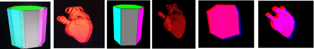
About 3D active Technology: In this technology, the two stereo images are created using the video card and the monitor. For this reason, a stereo effect cannot be defined here via an interface. It is set in advance by the stereo system developer, with values for the left and right eye, respectively: -0.01 and +0.01. It is possible to change the color of the system background through the interface. The background is white by default when the user is in traditional rendering mode. While in passive and active technology, the color is black. The goal is to make the objects stand out. Thanks to the Immediate Mode mode, it is possible to change the values of the parameters of the geometric figures using a text field, a slider, and keys. The proposed stereo system can generate, and at the same time visually present, both: java nodes in the case of polygons and polyhedra and files with the extension .obj. This way, arbitrary 3D models from various scientific fields can be visualized using immersive and non-immersive virtual reality devices. In this way, an accurate and complete picture of the studied object would be acquired. The system can import and export 3D files. Figure № 8 shows a regular hexagonal prism generated using geometry software. The object is represented in three ways: (3D active, 3D passive, and 3D traditional) perspectives. Also presented is a three-dimensional heart model for stereo visualization, downloaded from the following site: https://www.blendswap.com. It is preferable when observing a 3D file that the background offered by a virtual reality system is black. The aim is to make the model stand out in this way.
The visualization mode used through 3D active technology to implement the stereoscopic system is MixedImmediate. Geometric shapes created using the new boundary method are in Immediate mode. They are called once in the renderField() method. A Table №2 shows the methods for the 3D active technology mode. The most important of the four methods is renderField() – in this method, the 3D geometric objects that will be visualized by 3D active stereo visualization are called. It calls each of the objects that will be in Immediate mode.
A pair of glasses is required to realize 3D passive technology through anaglyph projection. With color, filters are blue and red for the right and left eyes, respectively. Each eye needs to have its own display for implementation through immersive HMD (virtual helmet) technology. For this purpose, two objects of type Canvas3D are created. Unlike planimetry, where the drawing of the geometric figure drawn on a piece of paper or board matches 100% with its original. Drawing the bodies from stereometry makes it very difficult for students, especially those who do not have well-developed spatial thinking. The problem is that the drawing transferred to a board, or a piece of paper can hardly be understood. This is where 3D technology, including (virtual reality, augmented reality, mixed reality, and 3D printing) comes to the rescue. In this way, students’ interest in mathematics would be strengthened, and their spatial imagination would be further developed. The stereoscopic system realizes two types of geometric objects, which are studied by stereometry.
- Edged geometric objects (polygon, prism, and pyramid) as shown on Figure 4 and Figure 5
- Cylindrical bodies (cylinder, cone, sphere, and torus)
The system enables the geometric object to be presented solid and wireframe. The second presentation will enable the student to understand the object’s geometry. At the same time, the dense presentation will allow its finished look. There is also a combination option between the two expressions.
Two methods are used to generate the geometric objects that are part of the stereoscopic system (traditional and new author’s boundary method). Both cases aim to generate a regular polygon, which is the basis for drawing the pyramid and prism. The traditional method is based on trigonometry using (radius, cosine, and sine). Characterizes the polygon with number of vertices and radius. The new method defines the polygon by the number of vertices and the side length [14, 15]. It is based on Isaac Newton’s method of limits and Cavalieri’s indivisibles. It uses only the relation of parallel segments. At the same time, it gives a more accurate result since it is not necessary to use the technique of extrusion and trigonometry involved in generating objects in programming and, in this case, in stereometry. The objects created in this way allow visualization through an immersive and non-immersive system and their representation as a .obj file. To illustrate the method, a regular hexagon will be considered as an example Table 3 and Figure 3. The same rules apply to polygons with the number of vertices increasing to infinity. The ratio of the parallel segments AB:FC =1:2 is determined, the length of the side of the polygon is represented by the parameter a. The regular polygon is placed in the center of the coordinate axis. The value of the height of the trapezoid FCBA is of value h. The Pythagorean theorem can determine it for triangle BCH; therefore, BH = a/2*sqrt(3). The height value is involved at four vertices of the polygon in the case of 6 vertices (A,B,D,E), defining values along the “y” ordinate (1,2,4,5).
- Prism construction
For the parametric representation of a regular hexagonal prism, it is necessary to do the following. The base is set, a polygon with 6 vertices with the length of the base through the parameter a. The parameter h sets the height of the prism. The bottom base is placed in the center of the coordinate axis, from which it follows that the values along the Z axis will be equal to zero. Vertices define the base numbered 1 to 6. The top base has vertices 7 to 12. The height rises along the z-axis. Therefore the values will be different from 0. Additionally, two more parameters h1 and h2 will be added, respectively. With the help of this, an inclined prism can be constructed; if they have a value equal to zero, the prism will be straight. An inclined prism follows at values where one parameter is zero and the other non-zero on Table №4.
Table 2: Java Mixed mode methods
| Mixed – mode methods | Pipeline |
| preRender() | Allow you to prepare any data structures for rendering |
| postRender() | After 3D rendering operation |
| postSwap() | Called once the rendered frame has been made visible to the user |
| renderField() | Useful in stereoscopic imaging. |
- Right straight/oblique prism
The algorithm for building a correct straight/slanted prism is as follows:
- A regular prism is selected from the object panel. The type of the two bases is chosen, which are regular polygons with 3 to 6 vertices.
- A length value is set for the main edge, then the multiwall is raised along the y-axis to set the height.
- The abscissa (or Z coordinate) value is checked. If the value is a non-zero number, the final result will be a slanted prism; otherwise, the prism is straight.
The primitives used to generate a regular polygon are a triangle, a quadrilateral, and a line for mesh representation. The .obj file information in the article is based on vertices and walls as shown on figures 6 & 7. The traditional way to color is by setting a material. Thanks to the new boundary method, it is possible to color the walls using the mathematical description of the objects using adjacent vertices expressed by the side length of the polygon and a suitable primitive. A disadvantage of the system is that when generating the .obj file, it is necessary to use a material, i.e., its body is set in one color.
Table 3: Regular polygon
| № vertex | X | Y | Z |
| 1 | -a/2 | a/2*sqrt(3) | 0 |
| 2 | a/2 | a/2*sqrt(3) | 0 |
| 3 | a | 0 | 0 |
| 4 | a/2 | -a/2*sqrt(3) | 0 |
| 5 | -a/2 | -a/2*sqrt(3) | 0 |
| 6 | -a | 0 | 0 |
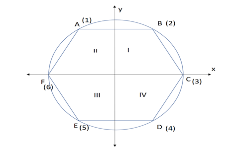
Figure 3: regular polygon with six vertex
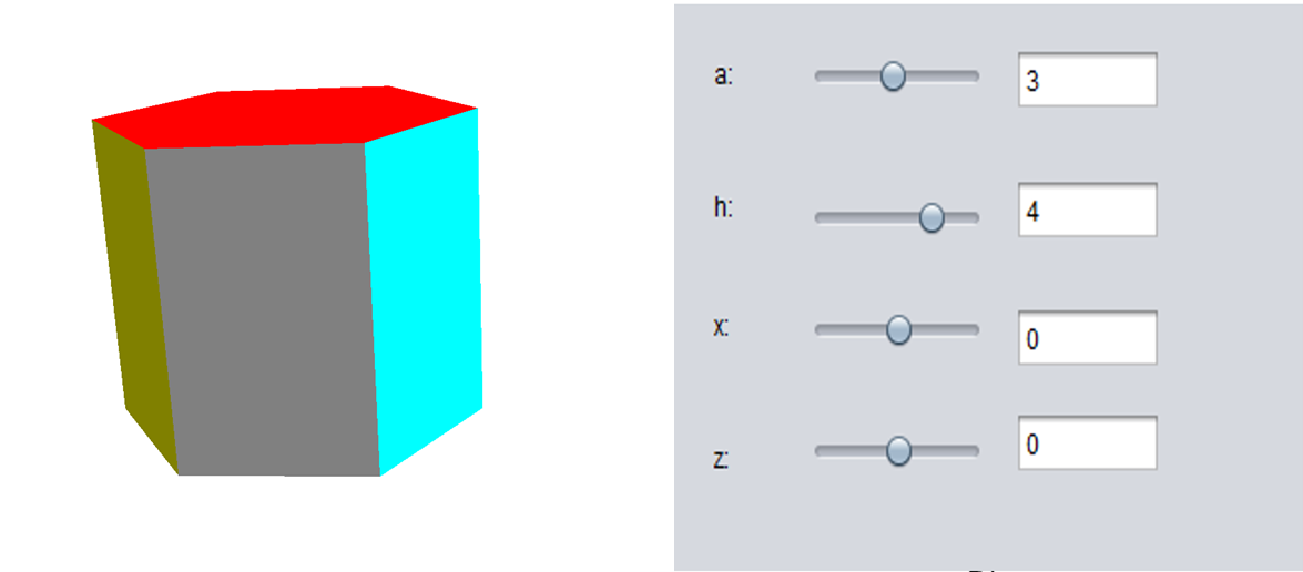 Figure 4: right regular prism
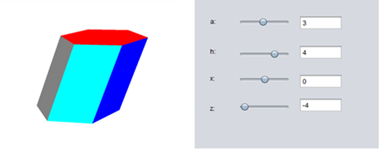
Figure 5: Tilted regular prism
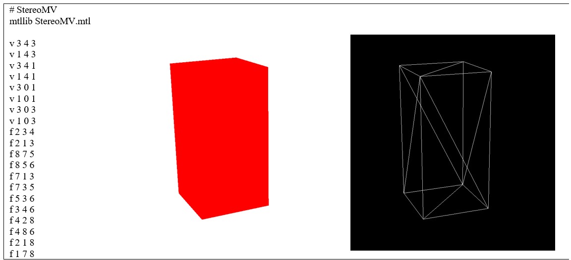
Figure 6: prism generated by primitive triangle
Table 4: Prism
| Number of vertex | X | Y | Z |
| 1 | -a/2 | a/2*sqrt(3) | 0 |
| 2 | a/2 | a/2*sqrt(3) | 0 |
| 3 | a | 0 | 0 |
| 4 | a/2 | -a/2*sqrt(3) | 0 |
| 5 | -a/2 | – a/2*sqrt(3) | 0 |
| 6 | -a | 0 | 0 |
| 7 | -a/2-h1 | a/2*sqrt(3)-h2 | h |
| 8 | a/2-h1 | a/2*sqrt(3)-h2 | h |
| 9 | a-h1 | 0-h2 | h |
| 10 | a/2-h1 | – a/2*sqrt(3)-h2 | h |
| 11 | -a/2-h1 | – a/2*sqrt(3)-h2 | h |
| 12 | -a-h1 | 0-h2 | h |
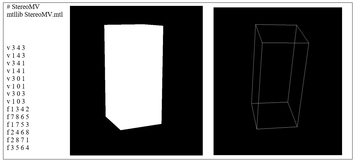
Figure 7: prism generated by primitive quad
(a)3D active b) 3D traditional c) 3D anaglyph
Figure 8: 3D Visualization
Table 5: Comparative analysis between 3D technologies realized by the new stereoscopic system
| Type of
Technology |
Type of system | Advantage | Disadvantage |
|
3D active/ 3D projector |
Without immersion |
– The colors are preserved
– Great stereo effect – Short program code – Applies to .obj and nodes – Easy connection to the stereo system |
– The stereo cannot be adjusted
– Requires expensive equipment – There may be incompatibility with the video card |
|
3D passive |
Without immersion |
– Applies to .obj and nodes
– The stereo can be adjusted with a slider – Does not require expensive equipment
|
– Does not retain primary colors (blue / red only)
– Small stereo effect – Long program code – Difficult to connect to the system |
|
HMD/CAVE |
With immersion |
– The colors are preserved
– Very large immersion effect – Applies to .obj and nodes – Easy connection to the stereo system |
– They are very expensive
– Long program code |
11. StereoMV The stereoscopic system
StereoMV is the result of a dissertation work on the topic “Stereoscopic training system”. It was originally developed for a non-immersive VR system using 3D active technology. Currently, the system can be visualized by an immersive system – an example being an HMD. A CAVE and semi-submersible FishTank system is also possible in the future. Table №5 provides a comparative analysis of the Virtual Reality systems discussed in this article. So far, the software is not yet finished. But at the same time, it continues to be further developed. The system can be used to visualize trimer models with VR from different domains. It also includes another direction – in medicine—the idea of creating stressful situations through a virtual environment. A mathematical analysis of recordings using a Holter device will be performed [16]. As well as a comparison of the data between recordings made by immersion and non-immersion systems. The goal is to be able to change heart rate and, from there, compare RR intervals to those at rest.
12. Conclusion
As is known, stereometry is a part of Euclidean geometry. Geometric figures are in three-dimensional space. Many students do not have a well-developed imagination to understand three-dimensional geometric objects. For the solution to this serious problem, a new mathematical software called StereoMV is presented in this paper. It allows students to view things in virtual reality. The main contribution of the system is that it can export geometric figures in files with the extension .obj. Then the three-dimensional model can be added to an augmented reality device or printed on a printer. The other innovation is that virtual systems with and without immersion can visualize the system. This will pique the interest of students. Studying the discipline of stereometry will become interesting, valuable, and enjoyable. This article performs a comparative analysis of virtual environment systems. Each of them differs in a specific way from one another. Some require more equipment, and others are relatively cheaper and offer an excellent stereo effect. Prolonged observation on the computer monitor through 3D active glasses can cause discomfort. Autostereoscopic monitors that do not require additional hardware come to the rescue. The Java programming language is used to implement the StereoMV stereoscopic system. Mixed immediate mode for stereo visualization through 3D active technology. Anaglyph projection is used for 3D passive technology with right and left eye color filters (blue and red), respectively. At this stage of system development, the immersive virtual reality that can visualize the software is the HMD (virtual helmet) device via head tracking. The system can export the objects in the .obj file extension. To add to a virtual or augmented reality device. As well as for 3D printing.
- P. Lebamovski, “Analysis of 3D technologies for stereo visualization,” in International Conference Automatics and Informatics, ICAI 2021 Proceedings, Varna: 206–209, 2021, doi:10.1109/ICAI52893.2021.9639534.
- Y. Lan, “Immersion, interaction and experience – oriented learning: Bringing Virtual reality into FL learning,” Language Learning & Technology, 24(1), 1–15, 2020.
- A. Yeh, R. Nason, “Toward a Semiotic Framework for Using Technology in Mathematics Education : The Case of Learning 3D Geometry,” International Conference on Computers in Education Melbourne, Australia, 2004.
- M. Nikolova, P. Byalmarkova, R. Radoeva, “3D technologies as electronic educational resource 3D technologies as electronic educational resource,” 2015(November).
- D. Minkovska, “Virtualna realnost – edin nov pogled kam savremennoto obuchenie,” 56(1), 64–72, 2013.
- J. Kang, B. Liu, “Application of 3D stereoscopic visualization technology in casting aspect,” China Foundary, (August), 308–313, 2014.
- N. Kim, M. Erdenebat, “3D Display Technology,” ©2013 Old City Publishing, Inc., June, 73–95, 2013.
- Y.Liang, H. Zhang, “Computer Graphics using Java 2D and 3D”, Pearson Education, 2003.
- A.Terrazas, J. Ostuni, M. Barlow, “Java Media APIS: Cross-platform Imaging, Media, and Visualization”, Sams, Indiana, 2002.
- K. Kerestes, “Making the anaglyph map,” 2000.
- “3D Технологии – Pro Screens, Oct. 2022”, [Online]. Available:http://www.proscreens.eu/bg/3d-technologies
- M.G.O. Brien, R.M. Levy, A. Orich, “Virtual immersion : The role of CAVE and PC technology,” CALICO Journal, 26(2)(January 2009).
- J.Q. Al-maliki, A.J.Q. Al-maliki, “The Processes and Technologies of 3D Printing,” International Journal of Advances in Computer Science and Technology, 4(10), 161-165, October 2015.
- P. Lebamovski, “THE EFFECT OF 3D TECHNOLOGIES IN STEREOMETRY TRAINING,” CBU International Conference Proceedings, 202, 68–74, 2021, doi:10.12955/pns.v2.155.
- P. Lebamovski, E. Petkov, “USAGE OF 3D TECHNOLOGIES IN STEREOMETRY TRAINING,” CBU International Conference Proceedings, 202, 139–146, 2020, doi:10.12955/pss.v1.61.
- E. Gospodinova, M. Gospodinov I. Domuschiev, N. Dey, A. Ashour, “Nonlinear analysis of heart rate variability in Type 2 diabetic patients,” Fractal Geometry and Nonlinear Analysis in Medicine and Biology, 1(4), 2016, doi:10.15761/fgnamb.1000123.