Field Oriented Control and Commutation Based on Sensorless Methods for High-Speed Electrical Motors of Unmanned Multicopters

Adv. Sci. Technol. Eng. Syst. J. 7(6), 58–69 (2022);
 DOI: 10.25046/aj070607
In recent years, unmanned aerial vehicles (UAVs), especially small and light multicopters driven by electrical motors and batteries, have experienced a boom in applications. The electrical drive system is a central component of these UAVs. This paper introduces the basics of these drives and presents control methods for them using permanent magnet synchronous motors (PMSMs). Control of these drives is based on field-oriented control (FOC) optimised for high speed (for instance, 200 el. krpm). For the multicopter drives, sensorless control is preferred, i.e., no position or speed sensor on the motors is necessary. Therefore, in this paper, the rotor position is estimated by a sensorless method based on a back electromotive force (back emf) observer combined with a start-up process. The parametrisation methods of the observer and the start-up process are described as well. The observer and the integration of it in multicopter drives are the major innovative parts of this paper. These introduced methods are verified by simulation and experiments. In experiments two motors are considered. One is applied to operate at the maximal speed up to more than 200 el. krpm. The other is a special UAV drive motor and applied for experiments with propeller, under similar operating conditions as UAVs. The results prove the performance and effectiveness of the introduced methods.
1. Introduction
1.1 Multicopters using electric motors
Unmanned aerial vehicles (UAVs), especially multicopters like the one in figure 1, have experienced a surge in popularity in recent years and have found application in various fields. UAVs powered by electrical motors are easy relatively inexpensive to assemble compared to other aircraft structures.
This paper is an extension of work originally presented at the 23rd European Conference on Power Electronics and Applications (EPE21 ECCE Europe), [1]. The technical background and addi- tional experimental results are included, as well as the analysis and discussion of the results1.
The electric drives and their corresponding control system are one of the core components of UAVs. They are required to be power-efficient, lightweight, robust against a hostile environment, and reliable over many flight hours. Surface mounted permanent magnet synchronous motors (SMPMSMs) are the most suited for UAVs for their compactness, high efficiency, and high power and torque density compared to other motor technologies. While com- pact multicopters with at least four motors are able to carry a light load, e.g. a camera, large multicopters with six or more motors can carry more equipment and are interesting for tasks such as package delivery in urban areas and the targeted application of fertilisers or pesticides on large farms. To provide the necessary thrust, the SMPMSMs for these large multicopters tend to have a high nominal current and a high number of pole pairs, for instance 20. Since multicopter propellers may be rated for top speeds of even 8000 mechanical revolutions per minute (mech. rpm), the electrical speed experienced by multicopter motors may easily surpass 100’000 electrical rpm (el. rpm).
When it comes to the control of motor current, field-oriented control (FOC) is preferred over e.g. block commutation mainly because of the more even torque generation and the higher power efficiency, especially when used with motors with a long electrical time constant. Either way, the direction of the rotor’s magnetic field must be known or measured for the control of motor current. While the most convenient approach consists in measuring the ro- tor’s angle with a position sensor, e.g. an encoder, it is possible
to infer the magnetic field’s direction by careful processing of the motor’s electrical quantities (voltage and current). This so-called sensorless form of position detection is advantageous for UAVs because it renders position sensors superfluous, thus reducing the overall weight and increasing reliability by eliminating a potential source of failure.
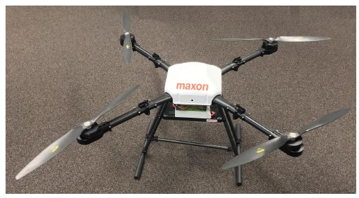
Figure 1: A test quadcopter (UAV)
At present, the high electrical speed and high motor current characteristic of large multicopters present a challenge for electrical drives, namely in terms of
- reliable sensorless position detection
- reliable commutation
- reliable current
1.2 Related work
There is much research focusing on design and build multicopters, for instance [2]. For a detailed introduction of PMSMs, [3] can be referred.
With consideration of sensorless control of PMSMs, the main approaches for sensorless position detection are two: one is based on the superposition of test signals (signal injection) on the voltage vector applied to motor. A number of research papers are published, [4]–[10]. For instance in [4], the Indirect Flux detection by On- line Reactance Measurement (INFORM) method is introduced. In [9], the rotor position of SMPMSMs without saliency is estimated by using periodic injection in circumference direction, interleaved with torque generating current. Whereas, the other is based on the estimation of the back electromotive force (back emf).
In this paper, less attention is paid to the signal injection meth- ods, which are computational intensive and may lead to disturbance of motor torque. The Position estimation based on back emf is suitable and sufficient for multicopter drives: as the motors must rotate continuously at high speed during flight, the back emf is large and thus easy to estimate with satisfying accuracy.
The simplest back emf estimation method entails detecting the instants at which back emf changes sign in each motor winding. However, this method cannot be applied in FOC but only in block commutation. A Model-based method using the sliding mode back emf observer is proposed in [11]. It is still only suitable for block commutation. In [12], a load torque estimation method for sensor- less control of brushless DC drives is presented, however it is also designed for 6-step commutation.
Further model-based methods compatible with FOC are the object of [9] and [13]. In particular, in [9] a back emf observer combined with signal injection is introduced. The algorithm can be improved and computation load of this method can be reduced for multicopter drives, with consideration of required operation speed. In [13], a sliding mode back emf observer is proposed for sensor- less position estimation, in which the position estimation error is compensated by using an integral sliding mode observer. However, for multicopter drives, varying effects have to be considered. Beside the dynamic response and high speed performance, the computation load may also be an issue.
In addition, the performance of sensorless control using pulse width modulation (PWM) and pulse-amplitude modulation (PAM) is analysed in [14]. The focus if this paper is only losses. The control performance is not included, which is very essential for UAV applications. Furthermore, the suggested advantage of PAM is significant at a high speed range compared that of multicopter drives.
1.3 Main contribution of this paper
As aforementioned, sensorless control of PMSMs is considered in a few papers, however, the special requirements and conditions of multicopter drives are taken into account, especially the sensorless drive at high speed range using FOC. With consideration that the multicopters is one of the most interesting application areas of elec- tric drive at present, therefore we propose and describe a control system for electrical drives for drives of multicopters. We achieve sensorless position detection with a Luenberger observer that esti- mates back emf. We propose a method to parametrise the observer’s gains to achieve a desired dynamic response and to guarantee a max- imum position estimation error at the maximum operation speed. The position estimate derived from the back emf in this way is updated at the rate of the current control task (25 kHz).
At high electrical speed, the two components of the motor cur- rent in the rotor coordinate frame are heavily coupled. While block commutation can obviate this [14], like others we add a decoupling mechanism in the current control loop [15]–[18].
After describing our proposed control system, we evaluate its performance by examining characteristics of interest of a selected multicopter drive (e.g. torque ripple) at its maximum electrical speed, both in simulation and experiment. We show that the multicopter drive with out control system can reach a speed of 200 el. krpm. To the best of our knowledge, other control systems for multicopters with these features do not exist at present.
The rest of the paper is structured as follows. The second section discusses the commutation method and explains the sensorless posi- tion detection method and the current controller designed for high speed applications. In the third section, the methods are verified by using simulations and experiments. The last section contains the conclusion.
2 Electrical drive systems
2.1 Power inverter and control
Drive systems using electric motors are very diverse. For PMSMs, the most widely applied motor drive is a voltage source inverter (VSI), [19], which is also applied in this paper. The topology of a VSI is illustrated in the Figure 2, left. The main components are the six metal–oxide–semiconductor field-effect transistors (MOSFET), T . They build three switching bridges for the three motor phases, respectively.
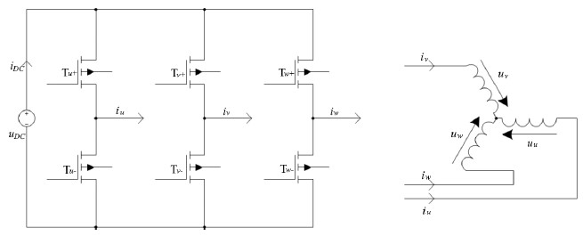
Figure 2: Structure of voltage source inverter and PMSM.
The motor winding terminals are connect to the outputs of the the ground by switching the power transistors in the left figure. In this paper, the switching pattern is determined according to space vector pulse width modulation (SVPWM) methods. Figure 3 shows simulated current in one motor phase and the corresponding PWM duty cycle as an example for generation of current using 5-segment SVPWM. The first plot illustrates the expected reference current. For an easier comparison with the actual current, the reference cur- rent is projected to the u v w phase coordinate. According to the SVPWM method the duty cycle is calculated and the switching sig- nals are generated, which are the third and fourth plot, respectively. Then, the generated actual current matches the reference current, shown in the second plot, except for the current ripples.
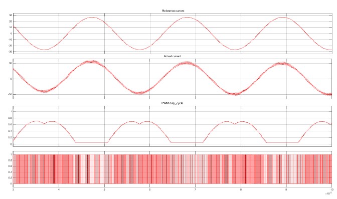
Figure 3: Example of generating current using PWM in one motor phase. The first plot, from above, is the reference current projected in u v w phase coordinate, the second is the actual current, the third and fourth are the PWM duty cycle and switching signal, respectively. In the figure of actual current current ripple can be observed, which is caused by PWM switching process.
As mentioned in the introduction, the motor current is regulated with FOC. The principle of FOC is to transform the total motor current flowing in the three phases into two orthogonal components, i.e., the torque generating and magnetic flux generating current by using the Clarke and Park transformations. An electric motor is a complex electrical-magnetic system. This transformations simplify this system significantly and allow the torque and magnetic flux to be controlled separately. Furthermore, the back emf observer mentioned in Section 3 is also implemented according to FOC, so that the estimated position, derived by the observer, can be applied for current control in FOC directly.
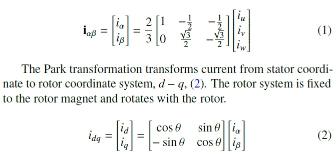
The Clarke transformation transforms motor current from phase coordinate, u v w, to stator coordinate, α β, (1). The stator coordinate is fixed with motor stator and the α axis has the same direction as the winding u.
The Park transformation transforms current from stator coordi- nate to rotor coordinate system, d q, (2). The rotor system is fixed to the rotor magnet and rotates with the rotor.
The aforementioned coordinate systems are shown in Figure 4. The angle, θ, between rotor and stator systems indicates also the electrical rotation angle of rotor, also known as commutation angle.
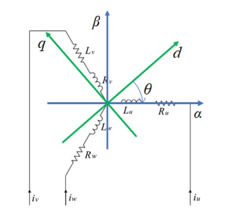
Figure 4: Coordinate systems applied in FOC, including phase, stator and rotor coordinate. θ is the angle between rotor and stator coordinate systems.
In order to control thrust, multicopter drives are operated in speed control mode. Therefore, the control system contains a PI speed controller cascaded with an PI current controller, see Figure 5. The speed feedback are derived by a speed observer or a speed filter. The configurations and gains of both controllers, observer or filter can be determined by using classical methods for electrical drives, for instance plant inversion or pole placement, [20]. As the algorithms and parametrisation methods for PI current and speed controllers are well known, they will not be introduced in this paper. The next subsections describe the features that are specific to operation at high speed.
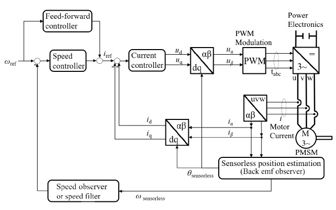
Figure 5: Control structure of multicopter drives, including speed and current control loops.
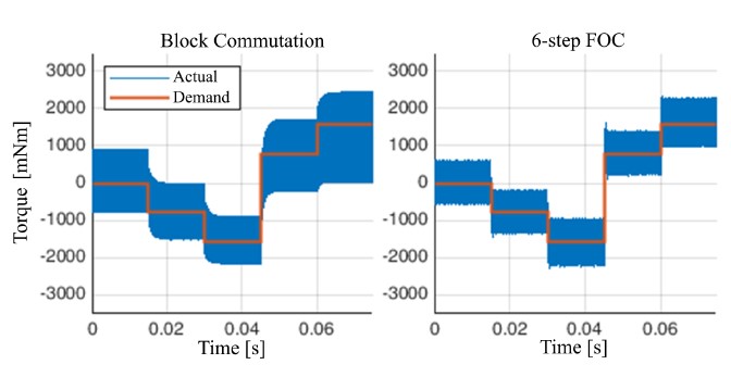
Figure 6: Simulated torque generation of block and 6-step FOC at 100 el. krpm. The FOC has faster response and smaller torque ripple compared to block commutation. The motor data are from PMSM 1 in Table 2 in the “Simulation and experimental results” section.
The output of the current controller, i.e., the demanded voltage, is converted to PWM signals via SVPWM generator. The PWM sig- nals then drive the DC to AC power inverter, which is also included in the top-right corner of Figure 5.
2.2 Commutation method
Since multicopter drives are powered by onboard batteries, effi- ciency is arguably the most important optimisation criterion. In this section, block commutation and FOC are analysed and compared. If the motor speed is high enough relative to the execution frequency of current control, FOC may only generate ten or even less consecu- tive voltage vectors per electrical revolution, which is comparable to block commutation (six states per electrical revolution). In order to make a fair comparison between the two commutation meth- ods, the position resolution is fixed to 6 per electrical revolution for both commutation methods in the simulation. The motor data from PMSM 1 in Table 2 in the experiment section is used for the simulation. The FOC current controller is explained in the “Current control with decoupling and delay compensation” subsection. Fig- ure 6 and 7 show torque generation performance at two different speeds. Figure 6 demonstrates that FOC has a faster response and lower current (torque) ripple. Besides, FOC is able to generate the demanded torque at a higher speed with the same supply voltage, see Figure 7. Therefore, FOC is chosen.
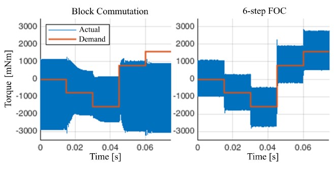
Figure 7: Simulated torque generation of block and 6-step FOC at 150 el. krpm. The FOC can generate the desired torque at 150 el. krpm, whereas block commutation fails. The motor data are from PMSM 1 in Table 2 in the “Simulation and experi- mental results” section. For block commutation to work at this frequency, a much higher DC supply voltage is needed.
As already mentioned, block commutation has the advantage that the rotor position can be inferred from the instant at which back emf changes sign (i.e., crosses zero) in the disconnected motor phase. However, this advantage is lost for motors with large electri- cal time constant operating at high speed: under these conditions, the current flowing through the body diodes in the leg of the power stage corresponding to the disconnected motor phase can shift the instant of the back emf zero-crossing.
Furthermore, for FOC, the PWM frequency and modulation methods are important parameters. In this paper, 5-level and 7-level space vector PWM (SVPWM) are considered, as shown in Figure 8. For the PWM frequency, 25 kHz and 50 kHz are considered.
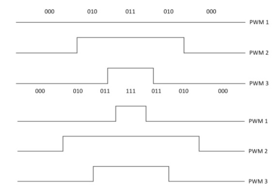
Figure 8: Example of 5-level (upper) and 7-level (lower) PWM duty cycle of a three-phase system. High and low, PWM1, PWM2 and PWM3 are according to the three phases respectively.
7-level SVPWM has lower current ripple, as shown in Figure 9. One should be aware that the difference of current ripple depends on motor characteristics, PWM frequency, and operating condi- tions. For motors with larger electrical time constant the difference becomes smaller.
of current and not of back emf. The prediction (4) and update (6) equations in discrete time are as follows
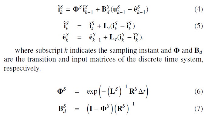
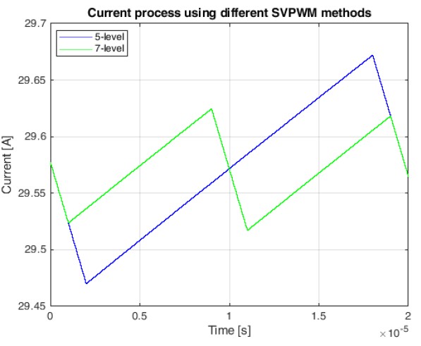
Figure 9: Simulated current process in a single PWM period using different modula- tion methods, current ripple of 7-level SVPWM is lower than that of 5-level.
On the other side, the switching losses on the motor controller significantly depend on the PWM frequency and modulation method. The comparison results in experiments are included in Section 4.
3 Motion control for high speed applica- tions
3.1 Sensorless position estimation
Li = diag li and Le = diag le are the observer feedback gain matrices for current and back emf, respectively. The ˜ and ˆ symbols indicate prediction and estimation variables, respectively. In this model, ∆t is equal to the sampling time Ts.
In order to determine the values of the observer feedback gains, the electrical control loop, i.e. the linearised innermost feedback loop in Figure 5, is analysed. This loop consists of the current controller, the inverse Park transform (to the right of the “Current controller” block), the motor electrical dynamics, and the back emf observer (“Sensorless position estimation” block). This loop is stable if and only if

where ϕ and bd are the diagonal elements of ΦS and BS in (3). Equation (8) indicates that the operating range of the motor is constrained as a function of the motor’s electrical dynamics and the observer gains. The ratio of voltage and back emf in the left-hand side of (8) we call operating point ratio. Because the constraint also contains the observer gains, the allowed operating range can be manipulated at least to a certain extent.
As mentioned in the introduction, the reliability of the drive system is improved and its weight is reduced by eliminating the position sensor. There are three fundamental requirements on sensorless position detection based on back emf estimation:
- Stability of the whole control system
- Accuracy of back emf estimation at low speed, which is essential to use the position estimate for current control
- Accuracy of position estimation, which affects the efficiency of torque
We choose to estimate back emf with an observer. The observer requires a model of the system. For this purpose, we consider the electrical model of a SMPMSM
The feedback gains of the observer are determined by using pole-placement with two conjugate poles. The available measure- ment is current and the expected output is back emf. For this reason, the transfer function in (9) from applied voltage, u, to back emf, e, has direct meaning in the controller and is applied. This transfer function is derived directly from the observer, according to the observer equations.
The back emf observer’s gains are calculated such that the phase where u and i are applied voltage and motor current, which are functions of time, R and L are the motor resistance and inductance matrices, and e is the back emf. The superscript S indicates that the quantities are expressed in the stator coordinate system.
As with most control systems in practice, ours is implemented on a microcontroller in discrete form. The discrete implementation of the observer contains two separate steps for prediction and mea- surement update. The observer differs from a textbook Luenberger observer because the update step is based only on the measurement
lag of the transfer function G(z) is below an predefined threshold at a certain frequency. This frequency corresponds to the maximum operating speed of the drive system expressed in Hertz. Because the phase lag of G(z) corresponds to the error in the estimation of the back emf angle, and thus rotor position, this criterion guarantees that torque generation efficiency lies above a desired threshold in the whole operating range.
The calculation of the gains entails placing the conjugate poles’ frequency a factor ten faster than the maximum intended operating
electrical speed. The corresponding expression for the observer’s gains is
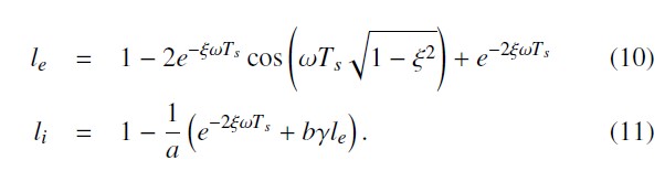
where ξ is the conjugate poles’ damping coefficient, ω their frequency in rad/s, and Ts the sampling period, which is equal to 40µs in the experimental system. To sum up, this method requires two inputs to calculate the observer gains
- Maximum intended operating point ratio for the present gain set
- Maximum intended operating speed for the present gain
With this parametrisation method, the position obtained from the back emf estimate is reliable enough for use in current control from a speed of about 300 to 500 rpm with most motors.
3.2 Operation process
The motor drive operates under two different operating modes, the start-up mode and normal back emf mode, as long as there is not any error in the drive system. The switching between the modes is illustrated in the algorithm below.
from the back emf observer for commutation, the rotation direction must be known. This is determined by taking the cross-product of the last two consecutive position estimates from the back emf observer. The scalar product of the motor speed with the unit vector z perpendicular to the stator coordinate (α-β) plane yields sk, which corresponds to the magnitude of rotational speed.
sk = (ek−1 × ek) · z. (12)
In practice, since sk is very noisy, it is low-pass filtered before evaluation of its sign.
3.3 Current control with decoupling and delay compensation
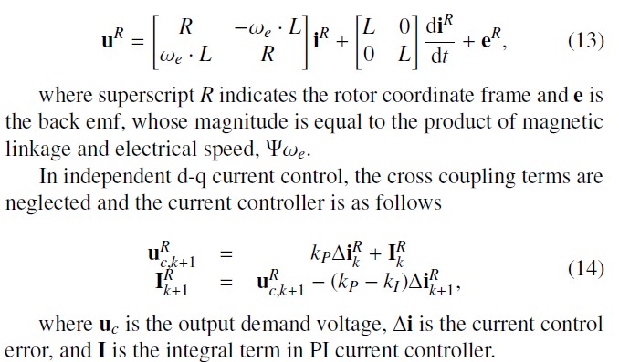
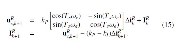
As mentioned in the introduction, cross-coupling between the current components in the rotor coordinate frame is proportional to the product of the motor’s electrical time constant and of the motor’s speed. If this cross-coupling is not considered when tuning the current controller, it deteriorates current control performance perceptibly. What’s more, the discrete implementation of the current control system inevitably gives rise to sampling delay. To counter-act the effect of cross-coupling and sampling delay in the current control loop, we apply d-q decoupling and delay compensation.
The derivation begins from the motor electrical model. Trans- forming the electrical model of PMSM in (3) to the rotor coordinate frame yields (13). The aforementioned cross-coupling between the ability of the back emf estimate for the purpose of current control. If it exceeds a predefined threshold, ek thr, the position obtained from the back emf estimate is used for control: we call this op- erating mode “back emf mode”. Compared to the speed range of propellers mentioned in the introduction (2000-8000 rpm), the speed corresponding to this back emf magnitude is low.
Algorithm 1: Operating process and modes
Below this speed, the motor operates in what we call the “start- up mode”: starting at standstill, a constant-magnitude current vector is applied whose angle rotates with linearly increasing speed, i.e., constant acceleration. This is an open loop control mode, since the actual position and speed are not measured. For propeller drives, the open loop start-up mode and the transition to closed loop back emf mode works reliably, since the load is known and light. In this way, the motor is accelerated until the back emf magnitude is sufficient for closed loop control.
In addition, one must be aware that the position estimated by the where uc is the output demand voltage, ∆i is the current control error, and I is the integral term in PI current controller.
When ωeL is comparable to or larger than R, independent con- trol of the current components of iR, i.e., id and iq, undermines transient performance and may even lead to instability. It is true that a higher control bandwidth can help. However, in practice the bandwidth is always limited by sampling frequency, which is determined by the computational power of the selected MCU and characteristics of the power electronics components.
We adopt the method in [17] to improve the performance of current control loop without having to increase the sampling frequency. Equation (15) describes the decoupling PI current control in discrete time.
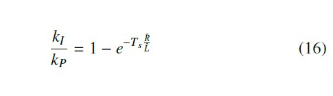
where Rˆ and Lˆ are the estimated values of phase resistance and inductance, respectively. They can be identified or obtained from the motor’s datasheet.
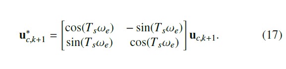
The sampling delay is another factor which affects the high- speed performance. It results in a lower torque than desired causing a worse torque generation efficiency. To address this issue, the demand voltage uc is rotated forward by Tsωe yielding u∗c , which is the final output of current controller
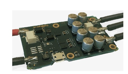
Figure 10: The UAV-ESC 52/30 without housing.
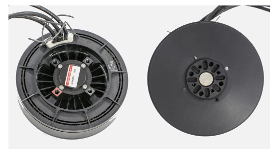
Figure 11: The test motor PMSM 1, UAV motor. On the back side, left, there are three thick motor power cables and four thin cables for two motor temperature sensors, which are applied for measurement of thermal behaviour later.
4 Simulation and experimental results
4.1 Simulation and experimental system
The introduced control methods are implemented in an Electronic Speed Controller (ESC), the maxon UAV-ESC 52/30, see Figure 10. The experiments are conducted using this ESC and two test mo- tors, PMSM 1 (Figure 11) is a Ø87 mm outrunner drone motor by maxon designed for multicopters, whereas PMSM 2 (Figure 12) is a general-purpose inrunner motor, also by maxon, which can reach a high electrical speed (210 el. krpm). The MCU of the UAV-ESC 52/30 is an ARM Cortex-M microcontroller from STMicroelec- tronics. The modelling and simulations are according to the same hardware systems under the Matlab/Simulink environment. Specifi- cations of the controller and test motors are summed up in Table 1 and Table 2, respectively.
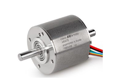
Figure 12: The test motor PMSM 2.
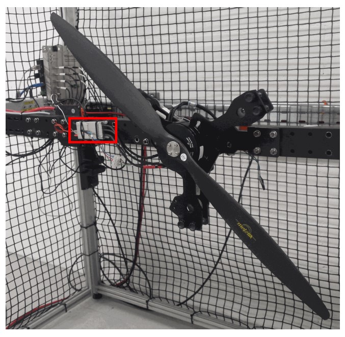
Figure 13: Experimental setup, including the test motor PMSM 1 with propeller and the controller with aluminium housing, indicated by the red rectangle.
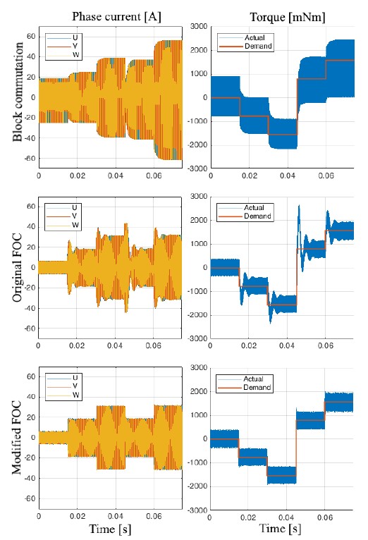
Figure 14: Simulation of motor current and torque during current step response at speed 100 el. krpm, using PMSM 1. The modified FOC has better transient performance and lower current/torque ripple compared to both block commutation and the original FOC.
Table 1: Controller specification
Type of controller maxon UAV-ESC 52/30 Mechanical dimension:
length 58 mm
width 36 mm
thickness 11.6 mm
Electric characteristics:
PWM frequency 25 kHz
Current control sampling frequency 25 kHz
Position estimation frequency 25 kHz
Speed control sampling frequency 2.5 kHz
maximum continuous operating current 30 A
maximum output current 90 A Supply voltage 12-52 V DC
Table 2: Maxon motor specification
|
Outer runner
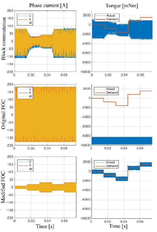
Figure 15: Simulation of motor current and torque during current step response at speed 150 el. krpm, using PMSM 1. The modified FOC performs well, whereas the block commutation cannot output the desired torque, and the original FOC becomes unstable.
The experiments are conducted with different loads. If the test motor PMSM 2 is used, the load is created by a coupled motor generating an opposing torque. On the other hand, the experiments with the test motor PMSM 1 are conducted with a propeller on the test setup shown in Figure 13. This paper concentrates on motor control.
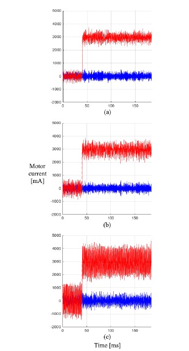
Figure 16: Motor current in experiments of current step response under current control using PMSM 2 at 40, 175, and 210 el. krpm in sub-figures (a), (b) and (c), respectively. The blue curve indicates the d-current and the red curve indicates the q-current. The current controller performs well, with increasing current ripple with operating speed.
4.2 Simulation results of control behaviour
The performance of current/torque control and commutation are simulated for different current step responses. In Figure 14, sim- ulations show that at 100 el. krpm, FOC has a fast response and generally smaller torque/current ripple compared to block commu- tation. Current control with decoupling and delay compensation
(“modified FOC” for short) has an even slightly smaller current and torque ripple compared to the independent d-q current control (“original FOC” for short). In particular, the modified FOC has a significantly better transient performance compared to the original FOC, with consideration of overshoot and settling time.
Figure 15 shows that at 150 el. krpm the original FOC becomes unstable. For block commutation, the DC supply voltage is not enough to correctly apply the desired torque. Instead, the modified FOC still performs well.
4.3 Experimental results of control behaviour
In experiments, different operating points and operating modes are included. Figure 16 shows current in the d-q coordinate frame. There are desired q-current steps at different constant motor speeds (140, 175, and 210 el. krpm), using the modified FOC and PMSM 2. The desired d-current is always zero. At the maximum tested speed, 210 el. krpm, there are 7.5 commutations per electrical revolution. The modified FOC is stable and sufficiently dynamic at all tested speeds, although current ripple increases with operating speed.
In Figure 17, the start-up process using PMSM 1 with propeller is illustrated. The drive starts from standstill in start-up mode. The magnitude of back emf is evaluated in each current period. As soon as the magnitude of back emf exceeds a predefined threshold, 0.35 V in this experiment, the operating mode switches to the back emf operating mode (at about 0.26 seconds in Figure 17). This back emf threshold corresponds to a mechanical speed of about 300 rpm. From then on, the position estimate obtained from the back emf estimate is considered reliable enough for use in closed loop control.
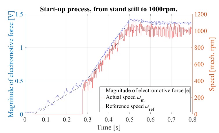
Figure 17: Start-up process from stand still to 1000 rpm , using PMSM 1 with propeller. The black dashed curve and red curve indicate the desired and measured speed, respectively. The speed in the plot is measured based on the back emf position estimation, which is available only after the switch into the back emf operating mode. The blue curve illustrates the magnitude of back emf. In this experiment, the threshold is 0.35 volts.
Further experiments of speed control are conducted. Figure 18 illustrates acceleration under speed control from 600 to 4000 rpm, using the PMSM 1 with propeller. The desired speed is implemented according to a profile acceleration of 5500 rpm/s. The drive oper- ates in back emf mode in this speed range. The speed control and position estimation are reliable.
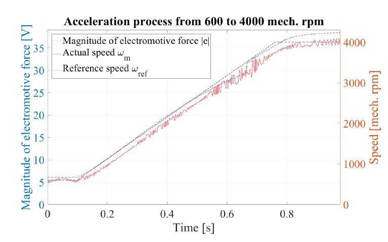
Figure 18: Acceleration using PMSM 1 with propeller, from 600 to 4000 rpm. The black dashed and red curves indicate the desired and measured speed, respectively.
Figure 19 illustrates speed control using fast acceleration from with stand still. The process of motor current is also included. The speed overshoot in this experiment is created with propose in or- der to illustrate a strong acceleration current, which exceeds the maximal continuous operating current for short period.
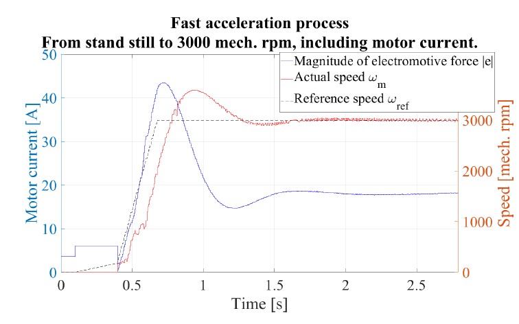
Figure 19: Acceleration using PMSM 1 with propeller, from stand still to 3000 rpm. The black dashed and red curves indicate the desired and measured speed, respec- tively. The blue curve indicate the motor current.
In the next experiment, true load condition of multicopters is tested. Figure 20 shows the speed control with a constant refer- ence speed, on PMSM 1 with propeller. For propeller drives, the propeller’s thrust and drag torque are both monotonic functions with respect to propeller speed. Therefore, at least under laboratory settings, the drive’s torque (current) will be a monotonic function of speed. In this experiment, the drive is tested at its maximum contin- uous operating current, i.e. 30 amperes under similar condition as that of true UAV applications.
To achieve this high fidelity in ground experiment, the motor is under speed control. The load torque is continuously disturbed by an external mechanism on purpose, oscillating between 10% of the maximum continuous torque. This leads to an effect that the controlled speed oscillates about 2.5%. The speed controller is not optimised for disturbance rejection. The speed control reference is about 3390 rpm, i.e., about 71.5 el. krpm.
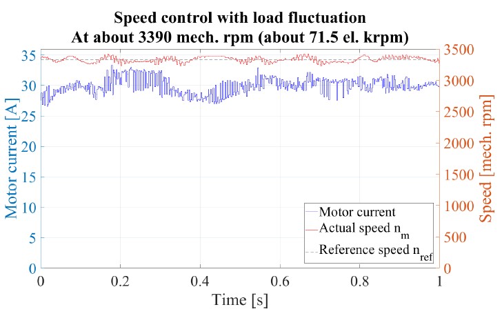
Figure 20: Speed control with maximum output power using PMSM 1. The load torque is continuously disturbed by an external mechanism, between 10% of the maximum continuous torque. The controlled speed oscillates about 2.5%. The black dashed and red curves are the desired and measured speed, respectively. The blue curve indicates the motor current.
4.4 Thermal behaviour
The thermal behaviour of the drive system is also experimentally in- vestigated. In this experiment, two motors are coupled, one operates as drive (PMSM 1 in Table 2) and the other as load. The tempera- ture of motor and power stage of motor controller is measured by using temperature sensors. A PT100 temperature sensor attached on one MOSFET in the power stage of the UAV-ESC 52/30 as shown in Figure 21. A NTC temperature sensor in the motor, shown in Figure 11, measures the temperature of the motor’s windings.
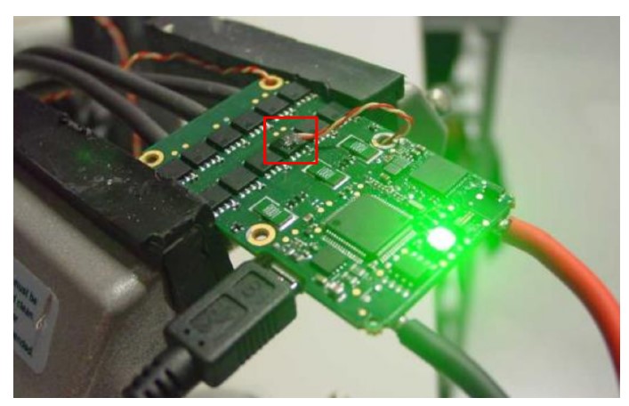
Figure 21: Installation of PT100 temperature sensor on a MOSFET of power stage, the red rectangle. There are totally 12 MOSFETs used in one UAV-ESC 52/30 controller. The red-yellow cables connect the PT100.
The results are summed up in Table 3 and 4, for motor and power stage, respectively, with consideration of using different modulation methods and PWM frequencies. The thermal losses are indicated by using relative temperature. The temperature using 7-level SVPWM with PWM frequency of 25 kHz is considered as reference temper- ature. The temperature difference is with respect to this reference temperature. It can be recognised that the applied 25 kHz, 7-level SVPWM is optimal for the combination of motor and power stage. According to Table 3, higher PWM frequency leads to lower motor temperature, and the temperature of 7-level SVPWM is lower than
that of 5-level SVPWM using the same PWM frequency. The reason is the smaller current ripple.
Table 3: Thermal losses on motor, indicated by relative temperature difference on motor. The motor temperature using 7-level SVPWM with PWM frequency of 25kHZ is considered as reference.
| SVPWM
method |
fPW M | |
| 25 kHz | 50 kHz | |
| 5-level | 3.7◦C | 0.3◦C |
| 7-level | 0re f | −0.8◦C |
For motor controller, the relative temperature of power electron- ics circuit is considered in Table 4. Analogously, the temperature of power stage using 25 kHz 7-level SVPWM is referred. Higher PWM frequency leads to higher power stage temperature, and 5- level SVPWM has lower temperature compared to 7-level SVPWM, due to less switching losses in the MOSFETs.
Table 4: Thermal losses on power stage, indicated by temperature difference of power stage. The power stage temperature using 7-level SVPWM with PWM frequency of 25 kHz is considered as reference.
| SVPWM
method |
fPW M | |
| 25 kHz | 50 kHz | |
| 5-level | −2.8◦C | 6.2◦C |
| 7-level | 0re f | 23.2◦C |
Comparing both tables, we can sum up:
- For the tested motor, increasing PWM frequency leads to significantly more losses on power electronics, whereas the reduction of motor losses is minor, because the multicopter motor has relatively large electrical time Therefore, the PWM frequency 25 kHz if preferred.
- At 25 kHz the 5-level PWM has slightly less losses in the power stage and slightly more losses in the motor compared to 7-level PWM. Because of the better accuracy of the out- put voltage using 7-level compared to 5-level SVPWM, the former is
That means the configuration of 7-level SVPWM at 25 kHz, as mentioned in Table 1, is reasonable for the multicopter drive controller.
5 Conclusion
As one of the most rapidly developed application areas of elec- tric motors, UAVs, especially multicopters, using electric motors have gotten a lot of attention. It is still a challenge to fulfil the requirements for professional multicopters, for instance for industry, agriculture and security applications. This paper focuses on these desires. Accurate sensorless control and commutation methods are developed in order to improve efficiency and extend the operation speed range.
In this paper, at first, a motor controller for multicopter drives is introduced. The technical background of electric drive systems
for PMSM is introduced briefly, with consideration of power in- verter, general control structure, commutation methods, including block commutation and FOC, and different modulation methods of SVPWM. The special requirements and operation conditions of multicopter drives are considered. Then, as the main innovative part of this paper, a control system for electrical drives for mul- ticopters is introduced. The control system relies on sensorless position detection provided by a back emf observer, on a decoupling mechanism of the motor current components in the rotor coordinate frame, and on the compensation of the effect of sampling delay in the current control loop. The parametrisation method of the back emf observer is also included in order to minimise the offset of estimated position, especially at high speed. The proposed methods have taken requirements and application situations of multicopter drives into consideration. The control system is implemented in a compact motor controller. We show in simulation and experiment that the control system can drive two motors at high speed, up to 200 el. krpm. In experiments, a compact motor drive platform, maxon UAV-ESC 52/30, is used. High fidelity validation with pro- peller and load with disturbance and oscillation are also included in experiments. Furthermore, the thermal behaviour of the multicopter drives is analysed. Measurement of the temperature of both motors and power electronics validate the choice of PWM frequency and space vector modulation method.
Besides multicopters, these methods can also be applied in other systems with similar requirements.
Conflict of Interest
The authors declare that there is not any conflict of interest.
Acknowledgement
The authors would like to thank their col- leagues in various teams of maxon motor ag, specifically, at the Corporate Center Motion Control for their collaboration, the Devel- opment Laboratory for access to the measurement installation and the multimedia files, and the Business Unit Aerospace.
- C. Zhao, W. Kong, F. Percacci, P. Gnos, “Sensorless FOC Drive Control Methods for High Speed Motors of Unmanned Multicopters,” in Proc. 23rd Conference on Power Electronics and Applications (EPE’21 ECCE), 2021, doi:10.23919/EPE21ECCEEurope50061.2021.9570534.
- N. Michel, P. Wei, Z. Kong, A. K. Sinha, X. Lin, “Modeling and validation of electric multirotor unmanned aerial vehicle system energy dynamics,” eTrans- portation, 12, 100173, 2022, doi:10.1016/j.etran.2022.100173.
- D. Mohanraj, R. Aruldavid, R. Verma, K. Sathiyasekar, A. B. Barnawi, B. Chokkalingam, L. Mihet-Popa, “A Review of BLDC Motor: State of Art, Advanced Control Techniques, and Applications,” IEEE Access, 10, 54833– 54869, 2022, doi:10.1109/ACCESS.2022.3175011.
- M. Schroedl, “Sensorless control of AC machines at low speed and standstill based on the ‘INFORM’ method,” in Proc. Industry Applications Conference, 270–277, 1996, doi:10.1109/IAS.1996.557028.
- A. Consoli, G. Scarcella, A. Testa, “Industry application of zero-speed sensor- less control techniques for PM synchronous motors,” IEEE Transactions on Industry Applications, 37(2), 513–521, 2001, doi:10.1109/28.913716.
- N. Bianchi, E. Fornasiero, S. Bolognani, “Effect of Stator and Rotor Satura- tion on Sensorless Rotor Position Detection,” IEEE Transactions on Industry
Applications, 49(3), 1333–1342, 2013, doi:10.1109/TIA.2013.2253437. - M. Laumann, C. Weiner, R. Kennel, “Arbitrary injection based sensor- less control with a defined high frequency current ripple and reduced cur- rent and sound level harmonics,” in Proc. IEEE International Symposium on Sensorless Control for Electrical Drives (SLED), 103–108, 2017, doi: 10.1109/SLED.2017.8078438.
- T. Slininger, M. Petit, H. Flieh, S. Chien, L. Ku, R. D. Lorenz, “Full Or- der Discrete-Time Modeling for Accurate and Speed-Independent Pulsating Voltage Injection Self-Sensing,” in Proc. IEEE 10th International Sympo- sium on Sensorless Control for Electrical Drives (SLED), 1–6, 2019, doi: 10.1109/SLED.2019.8896346.
- C. Zhao, M. Tanaskovic, F. Percacci, S. Marie´thoz, P. Gnos, “Sensorless posi- tion estimation for slotless surface mounted permanent magnet synchronous motors in full speed range,” IEEE Transactions on Power Electronics, 34(12), 11566–11579, 2019, doi:10.1109/TPEL.2019.2908408.
- K. Schuhmacher, S. Kleen, M. Nienhaus, “Comparison of Anisotropy Signals for Sensorless Control of Star-Connected PMSMs,” in Proc. IEEE 10th Inter- national Symposium on Sensorless Control for Electrical Drives (SLED), 1–6, 2019, doi:10.1109/SLED.2019.8896351.
- H. Fakham, M. Djemai, K. Busawon, “Design and practical implementation of a back-EMF sliding-mode observer for a brushless DC motor,” IET Electric Power Applications, 2, 353–361, 2008, doi:10.1049/iet-epa:20070242.
- A. Darba, P. D’haese, F. D. Belie, J.Melkebeek, “Rotor speed, position and load torque estimation using back-EMF sampling for self-sensing brushless DC machine drives,” in Proc. IEEE 5th International Symposium on Sensorless
Control Elect. Drives, 1–7, 2014, doi:10.1109/SLED.2014.6844968. - Y. Shao, B. Wang, Y. Yu, Q. Dong, M. Tian, D. Xu, “An Integral Sliding Mode Back-EMF Observer for Position-Sensorless Permanent Magnet Synchronous Motor Drives,” in Proc. 22nd International Conference on Electrical Machines and Systems (ICEMS), 1–5, 2019, doi:10.1109/ICEMS.2019.8922158.
- L. Schwager, A. Tu¨ ysu¨ z, C. Zwyssig, J. W. Kolar, “Modeling and Compar- ison of Machine and Converter Losses for PWM and PAM in High-Speed Drives,” IEEE Transactions on Industry Applications, 50(2), 995–1006, 2014, doi:10.1109/TIA.2013.2272711.
- F. Briz, M. W. Degner, R. D. Lorenz, “Analysis and design of current regulators using complex vectors,” IEEE Transactions on Industry Applications, 36(3), 817–825, 2000, doi:10.1109/28.845057.
- H. Kim, M. W. Degner, J. M. Guerrero, F. Briz, R. D. Lorenz, “Discrete-time current regulator design for AC machine drives,” IEEE Transactions on Industry Applications, 46(4), 1425–1435, 2010, doi:10.1109/TIA.2010.2049628.
- B. Bon-Ho, S.-K. Sul, “A compensation method for time delay of full-digital synchronous frame current regulator of PWM AC drives,” IEEE Transac- tions on Industry Applications, 39(3), 802–810, 2003, doi:10.1109/TIA.2003. 810660.
- J.-S. Yim, S.-K. Sul, B.-H. Bae, N. R. Patel, S. Hiti, “Modified current control schemes for high-performance permanent-magnet AC drives with low sampling to operating frequency ratio,” IEEE Transactions on Industry Applications, 45(2), 763–771, 2009, doi:10.1109/TIA.2009.2013600.
- D. Schro¨der, Elektrische Antriebe –RegelungvonAntriebssystemen, Springer- Verlag, 2009.
- D. Schro¨der, Leistungselektronische Schaltungen, Springer-Verlag, 2008.