Designing the MIMO SDR-based Antenna Array for 5G Telecommunication

Adv. Sci. Technol. Eng. Syst. J. 7(6), 167–173 (2022);
 DOI: 10.25046/aj070617
With the significant spread of 5G telecommunication systems, the demand for high quality of service and better coverage is growing rapidly. Multiple-input–multiple-output is planned to be among the key technologies in 5G telecommunication’s field. In this article, a new fully digital 2×2 MIMO testbed is implemented, using USRP B210 and 2 pairs of microstrip antennas with 4 radiation elements. In this implementation we cover the reconfigurability of the USRP combined with MATLAB, providing flexible integration between real-time and software host processing.
1. Introduction
Multiple-input–multiple-output becomes the most challenging technology in the 5G and the upcoming 6G telecommunication applications, given the ability of increasing the quality of communication and the rate of data [1], [2].
Multiple input multiple output (MIMO) has proven to be an important technique for communication systems. This technique benefits by using two or more antennas to transmit and receive data simultaneously, in order to increase the data rate and to provide a better reliability. So, MIMO provides the solution to the challenge [3], [4].
To develop a MIMO system, a microstrip antenna is designed, as well as is widely deployed in telecommunication systems due to its low profile, ease of fabrication and miniature size.
Much research such as [2]-[7] focus mostly on simulations and theorical analysis ignoring the system implementation because of its complexity, power consumption and low cost. the software defined radio has been found to avoid such limitations [1], [3]. More specially, by using SDR flexibility, reconfigurability and Rapid prototyping are covered to support new standards and protocols [8]-[10].
On this issue a new fully digital MIMO 2X2 has been implemented, this prototype is combining pairs of microstrip antennas with 4 radiation elements on both terminals.
For conveying and receive one or more types of wave signals simultaneously, An AM modulation is involved using Simulink and the flexibility, reconfigurability and low cost of USRP B210.
In our testbed, we investigate and profile the characteristics of USRP B210 platform including full steps such, transmission, modulation, spectrum, received signal and demodulation.
The rest of this document is arranged as bellow. Section II describes a comparison between rectangular and circular patch. In Section III, in order to perform the gain and assure circular polarization we moved on antenna array. In Section IV, we introduce an overview of our 2×2 MIMO testbed based on SDR. In Section IV, we define our SISO experimental results while analyzing our results. Even we report our novel model MIMO using AM modulation by studying our system’s performance, finally, in section V, we come to end the article.
2. Patch Antenna
2.1. Single element design geometry
The antenna is the first component of the MIMO system. This design uses patch antenna. Considering low profile, ease of fabrication, and low cost, patch antennas have proven to be the most frequently antennas [11].
Firstly, we start by a brief comparison between the most common shapes which are rectangular and circular configurations. FR4 epoxy has been chosen. Its relative permittivity is 4.4[12], in order to provide a balanced comparison.
In fact, both shaped microstrip patch antennas are performed using HFSS. The simulated antennas are resonating at 3.48 GHz.
Starting with the software designed version of rectangular shape which is shown on figure 1, its dimensions are 20 ×27 .
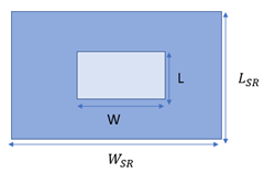
Figure 1: Geometry of the rectangular patch antenna.
In order to determine the microstrip patch antenna’s dimensions, the equations below have been used. Based almost entirely on the width and length of the rectangular patch, the design has been conceived [13][14].
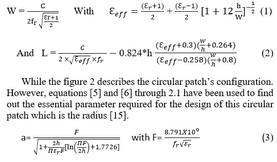
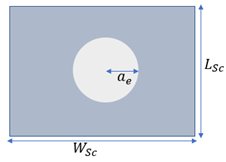
Figure 2: Geometry of circular patch antenna
2.2. Simulations results and discussions
It is clear from the figure below. both the graphs are resonating at the same resonant frequency (3.48GHz). Both shapes present a good adaptation. In fact, the rectangular patch provides a better result(50dB) by 3dB compared to the circular’s return loss(47dB).
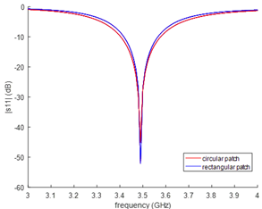
Figure 3: Comparison of return loss for different shapes.
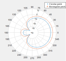
Figure 4: Comparison of 2D radiation pattern for different shapes.
For the antenna suitable for 5G telecommunication systems, a high directivity and a narrow beamwidth are both necessary.
As shown in figure 4, both designs present broadside radiation patterns. Indeed, at 3.48Ghz, the beamwidth shown by the circular patch antenna (90°) is narrower than the rectangular patch (100°). Moreover, the circular patch offers the highest gain value.
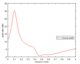
Figure 5: Simulated axial ratio (AR)
A circularly- polarized antenna is defined as having an axial ratio within 3dB at the required frequency.[13]
As shown in Figure 5, the axial ratio of the circular configuration presents an axial ratio AR ≤3 dB, with AR bandwidth (less than 3 dB,) is from 3.4 GHz to 3,7 GHz, in fact it reaches 0.7 dB at 3.48 GHz
According to HFSS simulation results, the rectangular shape provides better return loss, whereas the circular shape offers the enhanced gain, the smaller size and the narrower beamwidth.
Occasionally, a unique radiation element can meet the needs of the required antenna. But characteristics such beamforming beam steering, and beam scanning are usually achievable when radiation elements are arranged. So, in order to enhance its performance (gain, beamwidth), a compact 4-Element Microstrip antenna array is designed with the most efficient shape.
3. Array antenna
3.1. Antenna prototype
To increase the gain and directivity of the antenna, an antenna array interconnect two pairs of circular shaped antenna which is fed by a corporate-feeding network. It was implemented as the cascade of quarter wave impedance transformers with characteristic impedances , and to equally distribute the power. [12]
Indeed, to provide a good impedance adaptation, the quarter wave impedance transformers widths are given by the following equation [16].
To provide an equal power distribution and to adapt the impedance of patch elements, the quarter wave impedance transformers lines should be tapered.
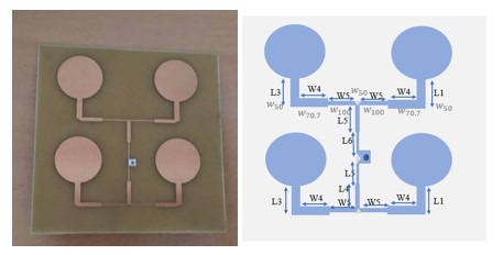
Figure 6: prototype of the proposed antenna array
The figure above describes the geometry of the proposed antenna array. In order to provide reasonable comparison, we kept the same substrate, the same geometry design and feeding network’s dimensions [12] with changing the patch’s shape. The dimensions of the antenna are illustrated below in millimeters (mm).
3.2. Discussions and results
Figure 7 shows a good agreement between the simulated and measured graphs except minor differences is observed. In fact, both designs deliver the minimum S11 of -30 dB. Indeed, obtain results for the antenna design reveals that the bandwidth of the fabricated antenna is shifted to 200 MHz different to the simulated bandwidth, it reaches 100MHz.
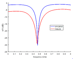
Figure 7: Comparative of simulated and measured S11 plot
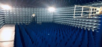
Figure 8: Radiation pattern Measurement
In order to check the electromagnetic field levels emitted by the antenna and to achieve more reproducible measurements, two antennas are fixed in the anechoic chamber. Whereas the first one is the reference antenna which is a QRH18 (QUAD RIDGEDHORN), the other antenna is dedicated to testing antenna in both E-plane and H-plane.
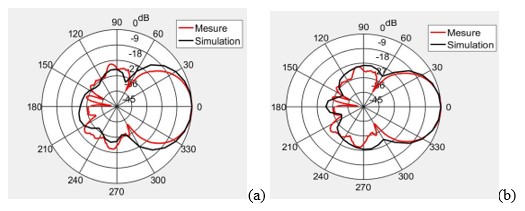
Figure 9: Comparison of the simulated and measured radiation pattern at 3.48GHz; (a) ?=90 (b) ?=0
The radiation pattern responses for both simulated and measured antenna are shown in figure 9. It can be clearly deduced that the prototype antenna is similar to simulation result. Compared to the single element antenna, the array antenna has the narrower beamwidth. In fact, the antenna array presents a directive radiation pattern. The bandwidth has reached to 40° as predicted in theory. It is also noticed that gain increases as the number of elements goes up. Therefore, the gain is around 5.8114 dB.
Unlike [12] our array antenna with 2 pairs of circular shapes provides a good gain, circular polarization and narrow beamwidth which is suitable for MIMO systems.
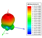
Figure 10: Simulated gain at 3.48GHz.
4. Conception of SISO
The USRP is a radio system conceived for implementation and rapid prototyping systems. [1] Selected because of its flexibility power consumption, low cost compared to other market options, reconfigurability, and high level of customization and high performance [17] [1], the USRP B210 has proven to be among the best choice for our work. Containing an RF front end complete with DACs and ADCs. The SDR attached to computer makes a full SDR system which enables the rest of the signal processing to be within MATLAB/Simulink.
4.1. Experimental setup
For our system prototype, due to the vast variety of supporting platforms, a USRP B210 is used, which provide fully-coherent MIMO 2×2 capability and low cost.
The transmission, reception, and processing of information testbed was performed in IRSEEM laboratory with no supplementary objects between Tx and Rx. The transmitter is located at a distance of around 1m from the receiver. The transmission was done in 3.48 GHz with using the USRP B210 devices which support RF frequencies from 70MHz to 6 GHz frequency. This boards are interconnected to our antennas array prototype via SMA connectors while ensuring a distance of λ/2 between the different Rx and different Rx to provide linear independence between different channels. So, with a carrier of 3.48 GHz, λ is around 85cm, where λ is the wavelength.
On the emission side, we sent a sinusoidal signal of frequency 1Mhz as a data signal to the input of Simulink then with using script of MATLAB via USRP, this data is multiplied by the modulation index, and after adding a constant, the resulting signal is multiplied with a carrier signal of frequency 3.48 GHz.
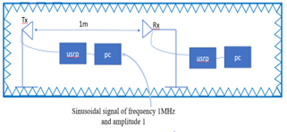
Figure 11: SISO Prototype
To create SDR MIMO applications, USRP B210, host computer and pairs of antenna arrays complete the hardware part of the SDR applications, The host computer is able to configure the USRP using software (MATLAB/Simulink), it enables users to transmit data using AM Modulation. Since, Simulink supports Universal Hardware Driver, it allows to control several parameters, such sample rate, gain, master clock, central frequency, interpolation factor, decimation factor…
So, first, we implement an AM transmitter based on sink blocks and standard blocks of Simulink to configure gain, center frequency, interpolation, filter and signal data [18] Simulink-USRP B210 enables the user to treat data in real time from USRP B210 and Simulink. Once the signal has been modulated, a spectrum analyzer called Agilent 4404B was interconnected to Tx (output of USRP B210) for displaying a signal in the frequency domain and check transmission problems.
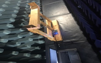
Figure 12: Implementation of SISO
4.2. AM transmitter
This model explains the basic concept/model of amplitude modulation using the USRP board with Simulink, in fact, our antenna array is interconnected to USRP to assure transmission of the signal. The USRP is interfaced also with the pc/ Simulink with an interface called Communications Toolbox supports to transmit and receive RF signals in real time, enabling the use of MATLAB and Simulink to configure radio parameters, design algorithms, generate waveforms and measure and analyze signals.
It is known that to transmit a signal by amplitude modulation, it is necessary to use a carrier at a frequency much higher which is in our case GHz than the data signal.
The amplitude modulation is done simply by the equation bellow
µm(t)cos (2π t) + cos (2π t) (4)
To build this equation with Simulink, the first part is modelled with Simulink but the second part is done with a block called USRP transmitter which allows to configure the USRP (gain, carrier frequency, interpolation factor).
In our case, we desire transmit a sinusoidal signal with a frequency . This signal must be converted into analog form, at the input of the USRP. therefore, the operating frequency of the DAC, or Master Clock Rate must be adjusted, and the interpolation rate operated by the Digital Up Converter above. The following values are possible for these parameters:
* Master Clock Rate: between 5 and 56 MHz
* Interpolation: an integer between 1 and 128, an even integer between 128 and 256, an integer divisible by 4 between 256 and 512.
*Master clock rate (Hz)= Baseband sample rate* Interpolation factor:
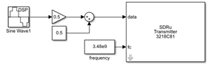
Figure 13: Transmitter model
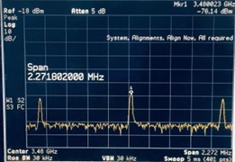
Figure 14: Spectrum
To verify the transmission of this sinusoidal signal, a spectrum analyzer in connected to the output of the USRP B210.
When the carrier wave is modulated, both sides of the stable carrier signal sidebands are formed which carry the actual information in the modulation.[12] This can be illustrated by Figure 14 when a strong carrier is on the carrier frequency (3.48Ghz) while the sidebands have a frequency on 3.48Ghz
As expected, the spectrum has the usual presentation: two sidebands are symmetrical on 3.481GHz and 3.479GHz and a powerful carrier signal is in the center. So, the data signal has been successfully transmitted.
4.3 AM Receiver
After finalizing the emission, another patch antenna array 2X2 is used as receiver.
For the demodulation part, we use an additional USRP device in order to demodulate the transmitted message using the receiver model.
Next, an overview of the AM demodulator is presented, which starts with the USRP receiver block. Then the demodulated signal can be passed to low-pass filter [17]. In fact, the low-pass filter, is used to remove the high-frequency signals and enable low-frequency signals to pass.[15],[17].
As before, the parameters of a block calling SDRu receiver must be programmed in order to recompose the modulating signal. In fact, we have kept the carrier frequency at 3.48. So, we will find two frequencies, the higher frequency will be eliminated by the low pass filter and the other one will allow us to extract the data.
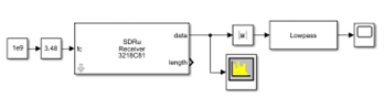
Figure 15: Receiver model
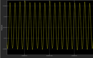
Figure 16: Received signal
The sinusoidal signal has been recuperated but there are fading due to the loss of system.
5. Conception of MIMO 2×2
The USRP B210 board is mainly designed using the following components :
– AD9361 transceiver;
– Xilinx Spartan 6 FPGA;
– The USRP toolbox.
The key component of the first section is the AD9361 transceiver. This block is responsible for using two receive and also two transmit channels for RF front-end processing. The transceiver contains zero-IF-to-RF conversion and feedback, ADC/DAC gain, decimation/interpolation and filtering.
To connect the transceiver to the FPGA a digital data interface is used and to transmit data between them the I\Q way is employed.
The second component describes the Spartan 6 and presents software host processing. It uses both signal channels due to combining 2RX and 2TX chains, so, it is definitely feasible to conceive 2X2 MIMO System based on SDR. For this effect, the user could program a specific modulator/demodulator script.
While the final part enables processing
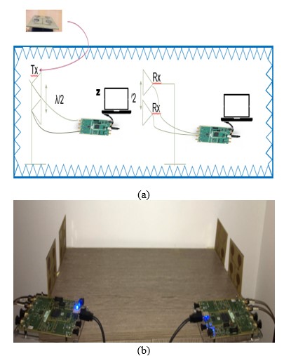
Figure 17: MIMO 2X2 System (a) illustrative schematic, (b)implementation
As second testbed, we propose a novel Simulink model for coherent 2×2 MIMO, interconnecting each USRP B210 with pairs of antenna array using SMA connectors at both in transmission and reception.
The Full digital MIMO 2×2 system is operating in band C where the digital signal processing is processed on baseband.
5.1. Transmitter
A data matrix received by the SDRu transmitter block will enables the signal waveforms for MIMO mode. Indeed, to use both channels, Channel mapping must be adjusted [1, 2]. And a block called matrix concatenation used as gateway between the block sdru transmitter and the data elements arranged in columns or rows.
The MIMO in this support package receives signals through the RX port and transmits signals through the TX/RX port.
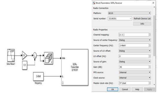
Figure 18: Programming USRP
5.2. AM Receiver
The USRP B210 below describes the hardware implementation framework for MIMO 2×2 model. In fact, for the reception part, the same model of SISO (AM receiver) has been kept, only a slight change with adding a block called select column in order to separate data and to treat each channel separately and simultaneously.
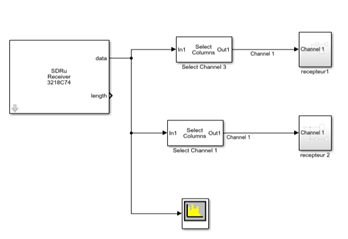
Figure 19: Receiving simultaneously
5.3-Implementation issues
In order to provide synchronization between both Tx antennas array and both Rx antennas array and to achieve interoperability between cards, The 2 Rx should operate synchronously, we send the sinusoidal signal from the first 2×2 antenna array and the same data from the second prototype antenna. It is very important to adjust the different parameters of both boards in a consistent way such as same center frequency value which is 3.48GHz, master clock, channel mapping, interpolation [16].
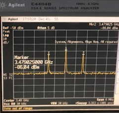
Figure 20: Frequency Spectrum of AM
The spectrum analyzer is connected to the output of the TX/RX port. As before, a strong carrier signal is centered at 3.48GHz, and the two sidebands are symmetrical at 3.481GHZ and 3.479GHz and the information signal is at 1MHz as shown in figure 19. So, MIMO transmission is well adjusted.
The sinusoidal signal with frequency of 1MHz have been usefully recovered. So, MIMO provide better efficiency specially in communications system.
In this work, performance of both MIMO and SISO systems is displayed. In fact, by transmitting the same data over multiple channels, MIMO introduce redundancy and diversity in data transmission that conventional single antenna (SISO) configurations cannot provide. This gives MIMO systems several advantages over conventional SISO configurations such the global throughput can be improved, allowing more quality and quantity data to be sent over the network, and using multiple data flow, problems such as fading caused by lost or dropped data packets can be reduced, this will help to recover all of the resulting data [16]
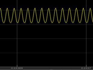
Figure 21: Received signal
6. Conclusion
In this study, a 5G-oriented MIMO prototype system has been designed and implemented equipped with four patch array antenna based on software-defined radios. The model for Amplitude modulation/demodulation has been developed combining USRP and Simulink in both SISO and MIMO Systems, with proving that MIMO is more efficiency than SISO. Moreover, all the analog and digital modules were properly developed and described enabling us to obtain a Full digital 2×2 MIMO system operating in band C. Finally, this system demonstrates great flexibility and scalability to be used in a wide range of applications. In the future MIMO beamforming system is investigated.
- S.Zhong, H.Feng, P.Zhang, J.Xu , H.Luo, J.Zhang, T.Yuan, L.Huang “Deep Learning Based Antenna Selection for MIMO SDR System,“ Sensors , 20, 6987, 2020, doi:10.3390/s20236987.
- Q. Wang, N. Mu, L. Wang, S. Safavi-Naeini, J. Liu, “5G MIMO conformal microstrip antenna design,” Wireless Communications and Mobile Computing. 2017, 1–11, 2017, doi:10.1155/2017/7616825.
- S.Zhong, S. H.Feng, P.Zhang, J.Xu, L.Huang, T.Yuan, Y.Huo, “User Oriented Transmit Antenna Selection in Massive Multi-User MIMO SDR Systems,” Sensors, 20, 4867, 2020, doi:10.3390/s20174867.
- M.Ali and M.Ibrahim, “Design Broadband MIMO Antenna to meet 5G communication systems requirements,” in 2021 IEEE 1st International Maghreb Meeting of the Conference on Sciences and Techniques of Automatic Control and Computer Engineering MI-STA, 838-842, 2021,doi: 10.1109/MI-STA52233.2021.9464429.
- G.K.D. Prasanna Venkatesan, T.Ranjitha, C. Shimona Neethi, S.Swetha, “Optimisation of mimo antenna for 5G applications,” International Journal of Advances in Scientific Research and Engineering (ijasre), 4, 133-139, 2018,doi:10.7324/IJASRE.2018.32642.
- R. Gandhiraj, Ranjini Ram, K. P. Soman, “Analog and digital modulation toolkit for software defined radio”, Procedia Eng, 30, 1155–1162,2012), doi: 10.1016/j.proeng.2012.01.975.
- G. N. Kareem, G. A. Gbotoso, S. O. Omogoye, “MATLAB analysis and Simulink model for amplitude modulation technique”, World Journal of Advanced Engineering Technology and Sciences, 2, 21-28, 202, doi: 10.30574/wjaets.2021.2.2.0035.
- O.Hiari, R.Mesleh, “A Reconfigurable SDR Transmitter Platform Architecture for Space Modulation MIMOTechniques,” IEEE Access, 5, 24214–24228, 2017,doi:10.1109/ACCESS.2017.2761859.
- D.M. Molla, H. Badis, L. George, M. Berbineau, ”Software Defined Radio Platforms for Wireless Technologies”, in IEEE Access, 10, 26203-26229, 2022, doi: 10.1109/ACCESS.2022.3154364
- M. Danneberg , I.Gaspar, M.Matthé, D.Zhang, L.Leonel Mendes,G. P. Fettweis,”Implementation of a 2 by 2 GFDM transceiver for robust 5G networks”, 2015 International Symposium on Wireless Communication Systems (ISWCS), 236-240,2015,doi: 10.1109/ISWCS.2015.7454336.
- T. F. A. Nayna, A. K. M. Baki and F. Ahmed, “Comparative study of rectangular and circular microstrip patch antennas in X band”, 2014 International Conference on Electrical Engineering and Information & Communication Technology,1-5, 2014, doi: 10.1109/ICEEICT.2014.6919142
- W. Chen, Y. Lin, “Design of 2X2 Microstrip Patch Patch Array Antenna for 5G C-Band Access Point Applications”, 2018 IEEE International Workshop on Electromagnetics Applications and Student Innovation Competition (iWEM), 1-2, 2018, doi:10.1109/iWEM.2018.8536673.
- M. Drissi, N. Benjelloun, P. Descamps, A. Gharsallah, “Multilayer antenna dedicated to MIMO Beamformig antenna for 5G telecommunication applications”, 2021 IEEE Conference on Antenna Measurements & Applications (CAMA) ,183-188, 2021, doi:10.1109/CAMA49227.2021.9703463
- Constantine A. Balanis, “Antenna Theory, Analysis and Design”, John Wiley & Sons, New York, 1997.
- L.B. Laskov, V. M. Georgieva, “Analysis of Amplitude Modulation and Demodulation in MATLAB Simulink Environment”. 2021 56th International Scientific Conference on Information, Communication and Energy Systems and Technologies (ICEST), 223-226, 2021, doi: 10.1109/ICEST52640.2021.9483470
- G. Fokin, D. Volgushev, A. Kireev, D. Bulanov and V. Lavrukhin, “Designing the MIMO SDR-based LPD transceiver for long-range robot control applications”,2014 6th International Congress on Ultra-Modern Telecommunications and Control Systems and Workshops (ICUMT), 456-461,2014, doi:10.1109/ICUMT.2014.7002144.
- C.Gavrila, V.Popescu, M.Alexandru, M. Murroni, C.Sacchi, “An SDR-Based Satellite Gateway for Internet of Remote Things (IoRT) Applications”,IEEE Access, 8, 115423-115436, 2020, Doi: 10.1109/ACCESS.2020.3004480.
- T.Liuski,” AM- ja DSB-modulaatioiden toteuttaminen Simulink- ohjelmistolla USRP- ohjelmistoradioalustalle ,phd thesis, University of Oulu, 2019.