Interference-Aware Nodes Deployment of a LoRa-Based Architecture for Smart Agriculture in the Southern Region of Senegal

Adv. Sci. Technol. Eng. Syst. J. 7(6), 248–255 (2022);
 DOI: 10.25046/aj070628
In Senegal, agriculture has always been seen as the foundation on which the socioeconomic development of the country rests. However, in the rural world, agriculture remains traditional at a time when the challenges of food self-sufficiency to accompany emergence are launched. In the southern part of Senegal commonly called Casamance, the abundance of rain makes it possible to practice rice cultivation and market gardening research must therefore play a leading role in the introduction of technological innovations, techniques, and decision-support tools to promote productive, competitive, and sustainable agriculture. Therefore, smart agriculture must focus on new solutions for water irrigation, soil quality, and culture monitoring. The emergence of the Internet of Things (IoT) is perceived as a very important lever for successful high-end intelligent agriculture. Indeed, the appearance of increasingly specialized monitoring sensors combined with new wireless communication technologies constitutes good decision-making tools. The proposal of this paper consists of a new network architecture that can cover a large cultivation area to carry out water irrigation techniques in Casamance. It is, therefore, a question of identifying the best communication technology among new Low-Power, Wide Area Networks (LPWANs) such as Long-Range (LoRa), SigFox, etc which is suited to the environment considered. Also, the choice of the best deployment of sensors for better coverage. The choice of technology must be motivated by the financial costs and the range of transmission. The deployment must fix the optimal distance between the sensors minimizing the interferences according to some parameters specific to the environment. An analytical study is used on the deployment to determine the optimal distance between two gateway nodes to reduce induced interference.
1. Introduction
Today, devices tend to replace humans in their daily work. This induces a permanent interaction between connected devices and humans. Internet of Things (IoT) [1,2] can now be considered one of the most powerful tools for creating, modifying, and sharing countless amounts of information. Indeed, the IoT aims to make objects dialogue with each other and with individuals. It has become an essential means used in many fields such as health [3],[4], agriculture [5], etc. In the case of smart agriculture [6], it is mainly used to modernize the sector. Indeed, the deployment of connected objects allows farmers to have real-time information on the quality of soil, water, plants, etc. So, it offers farmers and producers the opportunity to reduce waste and improve productivity [7–9]. This ranges from the amount of fertilizer used, and the number of trips made by agricultural vehicles, to more efficient use of resources such as water and electricity.
With new IoT tools, farmers can monitor their field conditions for real-time decision purposes. These decisions can be manual or automated according to the data collected such as humidity, light, temperature, crop health, etc. [10]. Innovations in terms of low consumption and connectivity make it possible to extend the scope of IoT applications for smart agriculture and to deploy connected objects in vast environments with strong constraints. Long Range (LoRa) [11] is a radio communication protocol that constitutes the architecture of the system and which allows low-speed but above all long-range data transmission for all your IoT-connected objects. LoRaWAN (Long Range Wide Area Network) [12] is a communication protocol that works over an LPWAN (Low Power Wide Area Network) network, while LoRa technology is the physical layer of the network. Casamance is a particular region that stands out from other areas of Senegal due to its enormous edaphic, climatic, hydrographic, and biogeographical potential. The high rainfall combined with very dense vegetation in the region makes it sometimes easier to use LPWAN communication technologies such as LoRa rather than 802.15.4 which is a short-range technology. This paper proposes a new LoRa technology-based network architecture suitable for a smart agriculture solution in the Casamance region of Senegal. The contributions can be divided into two major parts:
- A new LoRa network architecture based on the classical one combines short and long-range LoRa radio links for making it possible to carry out smart agriculture in rural areas, particularly in the southern area of Senegal.
- Evaluation of the proposal is conducted through an analytical study used on the deployment to determine the optimal distance between two gateway nodes to reduce induced interference.
The following presents the rest of the paper. Section 2 presents the context and the motivation, and the state of the art on smart agriculture is presented in section 3. Section 4 focuses on the LoRa networks while section 5 presents the proposed architecture of the network. In section 6, we present an analytical study followed by a discussion. Finally, the paper ends with a conclusion in section 7.
2. The context and motivation
Senegal is located at the most western projection of the African continent into the Atlantic Ocean, at the confluence of Europe, Africa, and the Americas, and a crossroads of major maritime and air routes. The climate is dry tropical and characterized by two seasons: a dry season from November to June and a rainy season from July to October. Three types of vegetation: forest in the south, savanna in the center, and steppe in the north. The southern part called Casamance is the rainiest part of the country. Casamance has a very varied range of soils:
- the tropical ferruginous soils leached with concretion and armor;
- weakly ferritic soils;
- undegraded halomorphic soils;
- and moderately organic hydromorphic soils.
The climate is humid tropical with rainfall above 1200mm which decreases towards the east. It is the wettest part of Senegal (rainfall > 800mm) thanks to the presence of the monsoon flow for more than 8 months and we find 20% arable land in the country. The area benefits from a hydrographic network made up of a set of permanent and seasonal waterways called bolongs. The main one is the Casamance River (350 km).
Basse-Casamance is the administrative region of Ziguinchor and is composed of forest areas and agricultural areas (mainly rice and peanuts). The forest areas are characterized by their density, particularly to the southwest of Oussouye covered with a Guinean vegetation cover made up of large palm groves, thousand-year-old cheese groves, lianas, teak, and giant mango trees. Up to the Gambian border, the forests, often state-owned, are dense and protected. The rice fields largely dominate the agricultural landscape of Basse-Casamance as shown in Figure 1.
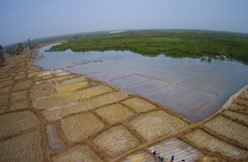
Figure 1: Rice fields in Casamance
Casamance is the richest agricultural region in Senegal. Agricultural production is also limited by the lack of large-scale mechanization and the inadequacy of agricultural inputs used.
Today, to win the challenge of large-scale agriculture, it is important to develop new digital tools capable of water irrigation, analyzing soils, proposing the best inputs, or making decisions in the face of warning messages, etc. To achieve this, it is important to make better choices on the sensor equipment. This must be motivated by the transmission range of the sensors, the financial cost, etc. In addition, the criteria for placing the sensors must be well studied to deploy the minimum number of sensor nodes for maximum coverage of the area. Otherwise, it is important to set up a network architecture capable of satisfying coverage and especially monitoring needs. A multi-linear architecture with LoRa radio links seems to be the choice to achieve smart agriculture in the specific case of Casamance. The main goal is to propose an end-to-end wireless LoRa architecture to collect the maximum data for irrigation or soil quality detection use.
3. The state of the art
Today, the world faces many phenomena such as climate change, floods, and threatening bush fires exposing certain particularly African populations to famine. Faced with these threats, it is necessary to find new effective methods to meet the challenges of food self-sufficiency. The democratization of the IoT has enabled digitalization in the field of agriculture. The sector is developing new tools to optimize the management of farms and harvests. This then makes it possible to set up intelligent methods of irrigation and water conservation [7,13–15], to measure the quality of the soil or crops [16,17]. Indeed, data and connected objects allow farmers to improve their productivity through network and data management models. The sensors deployed in agricultural areas are diverse and varied according to the characteristics including range, cost, etc. The sensors deployed in agricultural areas are diverse and varied according to the characteristics including range, cost, etc. Regarding the range, there are several types of 802.15.4 short-range wireless technologies or LPWANs such as LoRa, NB-IoT, SigFox, etc. Consequently, many authors focus on different models of networks for smart agriculture. The SAIoT is a model for smart agriculture described in [18]. The aim goal is to develop a real-time monitoring system for soil properties such as temperature, moisture, etc. The model is composed of three levels: the Farm level, the Server level, and the Client level. It implements also decision support advisory models for Pest & Disease forewarning, Crop Disease identification using image analysis and SMS (Short Message System) based alerts. Connected objects used to collect information use 802.15.4/Zigbee radio links, which therefore limits the range of the solution to small areas. The authors of the paper [19] present another application of smart farming. It consists of an intelligent irrigation system based on 802.15.4-type sensors. The sensor nodes are deployed in a restricted space of over a hundred meters. LPWAN technologies seem to be best suited to large agricultural areas due to the long transmission range. Studies have recently been conducted in this direction to see the contribution of these wireless technologies in smart agriculture. The paper presented in [20] reviews the most used LPWANs in the case of smart agriculture. It presents the Nb-IoT, Sigfox, and LoRa technologies with the characteristics. NB-IoT is an LPWAN solution based on existing cellular networks. In public mode, the principle of LoRa is similar to Sigfox. Transmitters once positioned in an area covered by the network will send their information directly to the Cloud of the LoRa or Sigfox operator. This requires that each sensor be provisioned with a subscription from the operator to be able to communicate with the Cloud. LoRa technology also offers the possibility of operating in private LoRa mode. This means it is possible to build your own LoRa network using gateways for local coverage. No need for subscriptions with operators in private LoRa mode. This mode of operation of LoRa is very interesting in the case of vast agricultural areas devoid of operator network coverage, in particular, called white areas. This explains why a lot of work in the field of smart agriculture uses solutions based on LoRa. An efficient LoRa-based smart agriculture is presented in [21] for humidity and temperature monitoring uses. In [22], the authors present novel watering management based on sensor nodes using LoRa technology for communication. The solution is designed for the specific case of Vietnam and real-time data management. The model describes three types of nodes. The gateway node performs the core functions of data collection from the nodes via LoRa. Node 1 and sensor node 1 has been designed to act as a relay between node 1 and the gateway Nodes 1 and sensor 2 have been designed to act as a relay between node 1 and the gateway while node 2 monitors the quality of the water coming from the pump. The authors present an architecture composed of LoRa nodes for monitoring roles, a gateway for data collection, and a server for and a server for data analysis and decision-making. They evaluate the architecture in terms of humidity and temperature. Another very important factor in agricultural monitoring is the physical topology of the area. Indeed, it can determine the way to deploy the nodes in the zone. Most agricultural areas in southern Senegal are surrounded by waterways for much of the season. In such a configuration it is easier to carry out a deterministic and linear deployment of the nodes. In addition, given the very large size of these areas, it is necessary to opt for equipment with a long communication range. In this context, linear LoRa networks are more suitable for the considered environments. The advantage of linear wireless networks resides above all in their simplicity of deployment. However, in the specific case of linear LoRa networks, it is important to rethink this deployment taking into account the characteristic parameters of LoRa such as range, data rates, propagation model, etc. Much research on the deployment of nodes in wireless networks has been proposed over the years. Very recently, they have turned to LoRa-type wireless networks. Paper [23] presents a LoRa network of campuses deployed on several sites. It describes a method of deploying LoRa sensors to cover communications. The network covers an area of 20,000 meters. Because of the scope of LoRa nodes, it would be more interesting to be able to deploy the nodes over a wider area. In paper [24], it is about covering the city of Southampton in the UK using a LoRa network. The deployment method used in this paper focuses on the optimal distance between gateway nodes that can ensure maximum network coverage. The connectivity assessment tested the efficiency of the deployment with the message delivery rate. Interferences if not well managed can negatively impact the deployment of LoRa nodes. In the paper [25], the authors present a modeling of interferences based on a mathematical model. The analysis of parameters such as the SIR or the SNIR provided a clear idea of the impact of the propagation model on interference in LoRa networks. However, the work carried out was done over a radius of 12 km, which is insufficient in the case of vast agricultural areas. An interference study was conducted from an anechoic chamber to give an idea of large-scale deployment. The evaluation of parameters such as the spread factor [26], and the coding rate [27] sets the conditions for deploying nodes. Other works focus on the deployment of LoRa networks based on criteria different from those mentioned so far as in [28]. This paper evaluates the impact of interference on deployment in terms of BER [29] according to various spread factors, coding rates, and bandwidth
As indicated above, the LoRa technology seems to be the most appropriate in the particular case of the Casamance context. Indeed, the transmission range is around 20 km and the possibility of configuring it in private mode makes it possible to cover vast agricultural areas without an operator network. The other advantage of LoRa is the reduction of financial costs. In the following, we review LoRa technology. This is to explain in detail the physical and logical components of the LoRa architecture.
4. An overview of the LoRa technology
Like LPWAN networks, the LoRaWAN network uses a star topology configuration. The architecture of a LoRa network is essentially composed of four components: end devices, gateways, a network server, and an application server. Figure 2 shows these different elements. The end devices are equipped with LoRa modules to allow them to send and receive radio signals and communicate with the gateways. In addition to being able to exchange with the end nodes, the gateways have an interface that allows them to have TCP/IP-based communication with the network server. The network component that has the most work to do is the network server. It allows the administration of the whole network, in other words, it is the conductor. Its role is to route information from the end nodes to the corresponding application servers and to remove redundant packets.
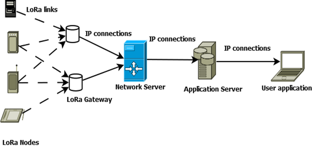
Figure 2: Classic LoRaWAN architecture
4.1 The LoRa physical layer
LoRa is based on spread spectrum modulation which uses the Chirp technique signal in which the frequency increases (up-chirp) or decreases (down-chirp) with time. Spread spectrum is a technique that allows an information signal to be transmitted over a bandwidth several times greater than the minimum bandwidth required. The modulated signals have a constant amplitude with a variable frequency [30]. Spread spectrum modulation reduces energy consumption and increases resistance to interference. In LoRa, signals are modulated in the ISM (Industrial, Scientific, and Medical) frequency band without a license, which varies according to the region (e.g. 868 MHz in Europe, 915 MHz in North America)[30].
The performance of LoRa nodes depends mainly on the following parameters:
The spreading factor (SF) is a quantity defined by the ratio between the chip rate and symbol rate. A chip represents pulses of a spread spectrum code and a symbol represents several chips. A chirp contains 2SF bits per symbol. In a LoRaWAN network, the spreading factor is an integer between 7 and 12 [31]. This parameter allows us to vary the transmission range and rate and to send simultaneously on a given channel. A high spreading factor implies a long transmission range and a low data rate (see Table 1).
Table 1: LoRa spreading factor
| Spreading factor (for UL at 125 kHz) | Bit rate | Range (Depends on Terrain) | Time on Air ( for an 11-bytes payload) |
| SF10 | 980 bps | 8 km | 371 ms |
| SF9 | 1760 bps | 6 km | 185 ms |
| SF8 | 3125 bps | 4 km | 103 ms |
| SF7 | 5470 bps | 2 km | 61 ms |
Bandwidth is the difference between the maximum and minimum frequency. High bandwidth values result in high data rates. The transmission time of a symbol (Ts), the spreading factor, and the bandwidth (BW) are related by the following equation,
Coding rate: LoRa uses the FEC (Forward error correction) technique to detect errors in transmitted frames. Extra bits are added in the frame, more precisely at the payload level. In LoRa these extra bits are controlled by the coding rate (CR). The values that the code rate can take are 4/5, 4/6, 4/7, or 4/8 [30].
4.2 The LoRaWAN protocol
LoRaWAN (Long Range Wide Area Network) is an open protocol proposed by LoRa Alliance (the Organization in charge of the promotion of LoRaWAN). It corresponds to the MAC (Medium Access Control) layer of the OSI (Open Systems Interconnection) reference model. LoRaWAN is designed to connect objects equipped with LoRa modules and powered by battery energy to the Internet. A LoRaWAN network consists of LoRa nodes, gateways equipped with LoRa modules, and an interface for connecting to the Internet, a network server, and an application server. LoRaWAN uses the channel access technique of the ALOHA type [12]. That is, each node in the network can transmit whenever it wishes. According to the LoRaWAN specification [10], Data transmission is performed on multiple channels. Indeed, each device has a maximum of 16 channels that can be preconfigured before a terminal joins a LoRaWAN network. A LoRa frame consists of a preamble, a header, the payload, and an error control field. If the header contains information about the CRC (Cyclic Redundancy Check) and the CR (Coding Rate), the frame is said to be explicit, otherwise, it is implicit.
The LoRaWAN specification defines three modes of operation for end nodes suitable for various IoT applications. Each mode of operation is commonly referred to as a class.
Class A: This is the default class that must be implemented by all end nodes in the LoRaWAN network. In class A, the terminal sends a message to the network server (uplink) through a channel randomly chosen among those configured in the terminal with a data rate, the terminal node opens two reception windows RX1 and RX2 respectively after one second and 2 seconds (default values) following the uplink transmission during which it waits for the server transmission (downlink). If the server does not transmit, then the message is resent. The recommended retransmission limit is eight (8). Due to the short listening window, class A is the most energy efficient.
Class B: Terminals, where class B is enabled, consume more power than those implementing class A because these terminals offer more receive windows. The ping slots are opened at regular time intervals to activate the downlink. They are synchronized through a beacon broadcast in the network to provide the synchronization references. The synchronization time is called BEACON_PERIOD. In addition to these specific features, class B also implements the operating mode of class A.
Class C: Terminals using class C are constantly listening to the channel to receive messages from the network server. In a terminal, class C and class B should not be activated simultaneously. Unlike Class B, which opens only two receive windows, Class C additionally opens an RXC receive window for continuous listening.
As we have already shown, LoRa through its physical and logical components is an ideal candidate for smart agriculture in a country where network coverage is not guaranteed in agricultural areas. Moreover, given the abundance of rainfall and the physical architecture of agricultural areas, it is more judicious to arrange the sensors linearly because of the constraints imposed by the environment. Indeed, arable land is surrounded by waterways. So, for the needs of traceability and economy, it is preferable to deploy them linearly. The works cited above have already shown the interest that researchers have developed in such architecture. It should be noted however that the classical architecture of LoRa as it is presented cannot guarantee good coverage in the particular case of Casamance. The very complex nature of the landscape due to the high rainfall does not guarantee good wired deployment between the gateway nodes and the routers. Indeed, to succeed in such a deployment, specific devices are needed that can protect the cables over long distances, which is likely to be very expensive. The deployment of sensors must take into account several factors such as the extent of the area, the absence of telecommunication operators, and the financial costs. For all these reasons, it is therefore judicious to propose an architecture for deploying sensor nodes in a linear mode without a wired connection. In other words, the proposed architecture combines LoRa radio links throughout the network with short- and long-range links.
5. The proposed architecture
The contribution of this paper is the implementation of a network architecture based on LoRa for the needs of smart agriculture. Such an architecture must take into account the specific characteristics of the area considered, the financial costs, etc. For all these reasons, the architecture is composed of several types of nodes with different physical characteristics. It is therefore a multi-linear architecture composed of several levels combining short-range and long-range nodes depending on the level as shown in figure 3. The choice of the linear topology is explained for the needs of ease of deployment and location of the nodes, and the complexity of the relief. Indeed, as indicated above, the vegetation in Casamance is very dense and very diversified. Several types of end device nodes can be described according to their role.
- Some sensors measure the rate of wetting on the leaves to anticipate diseases related to leaf humidity and reduce the use of phytosanitary treatments.
- Some sensors measure soil humidity and temperature to control root irrigation and delay the arrival of pests.
- Some measure humidity and air temperature to detect frost, and anticipate the life cycle of insects and diseases.
The end device nodes form the first level and the gateways the second level. Each gateway plays the role of cluster head for all the nodes associated with it. There are mainly two types of links in the network as shown in figure 3:
- Low LoRa links: The Low LoRa links are short-range links, and are used in communications between the nodes of the first level and those of the second level. SF parameters in [7, 8] are used.
- High LoRa links: The high LoRa links are long-range links, and are used in communications between the nodes of the second level in the sink node. SF parameters in this case are in [9, 10, 11].
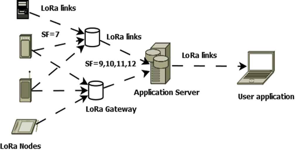
Figure 3: Proposed network architecture
Such architecture faces several challenges. In particular, the challenge of deployment for better optimization of resources such as memories, storage spaces, or computing units. It is well-known that interference in wireless networks can negatively and significantly impact performance. Therefore, in such a network, it is imperative to settle the question of deployment to minimize interference. Figure 4 below gives an illustration of the node’s deployment in a rice field in Casamance. In the following, we present an analytical analysis method to define an optimal deployment of network nodes.
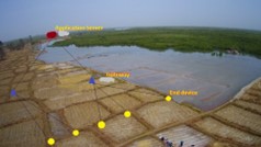
Figure 4: Illustration of node deployment in a rice field
6. Analytical study and discussion
The objective of this study is to define a method for deploying the nodes of the architecture described above. It is therefore a question of defining from certain well-chosen parameters the minimum distance between two gateway nodes which makes it possible to achieve the best deployment. These induce the choice of the spreading factor, the bandwidth, the coding rate, etc. A good interference management policy makes it possible. We can identify the case where there is a risk of interference at the node Gi, interference induced by the activity of the node Gj. We can define the gateway node Gj and the set of nodes j as the interfering nodes for the node Gi. In this condition, an optimal node deployment needs to set a minimum distance between two gateways. In wireless networks, the SIR (Signal-to-Interferences Ratio) [32] is a good indicator of the quality of the received signal. Thus, depending on the desired reception power, it is possible to rely on the SIR to determine the optimal distance between two nodes. In the specific case of this paper, the analysis must determine the optimal distance between two gateways to minimize interference. Indeed, given the proposed architecture, we can consider the gateways as cluster heads. Thus, the distance between the gateway nodes has a significant impact on the deployment.
The cluster i is formed by the gateway Gi which is the cluster head and the set of nodes ni. In the same way we define cluster j as shown in figure 5. To determine the minimum distance between Gi and Gj , we set:
- Ti: the transmission power of node i
- Tj: the transmission power of node j
- the transmission power of node Gj
- di: the distance between node i and gateway Gi
- dj: the distance between node j and gateway Gi
- dij: the distance between gateway i and an interfering gateway
- d: the distance between two adjacent gateways
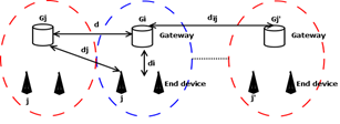
Figure 5: Distance between gateway illustration
The propagation model represents the signal and therefore the interference induced during transmission. To take into account the environmental fluctuations of the medium, Log Normal Shadowing is required in this study because of its random nature. The path loss at an arbitrary distance from the transmitter is given by the following equation (1):
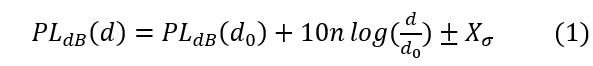
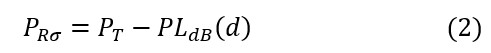
where n is the path loss attenuation factor, is the path loss at a reference distance , and is a zero-mean Gaussian distributed random variable. The standard deviation σ is expressed in . So, for a given transmission power PT, the received power is provided by the equation (2):
The received signal at the gateway Gi from node i is the sum of multiple terms: the first, is the desired signal received from node i; the second is the interferences caused by the set of gateways Gj around Gi, the third is the interference generated by all the sets of nodes j associated to the gateways Gj. Let be the set of node j associated with a gateway Gj. We can define the SIR [20] as:
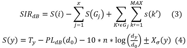
y can be a gateway or an end device node, x is the number of interfering gateways for the gateway Gi and MAX is the number of nodes associated with a given gateway.
The coexistence of several radio links of different ranges is a particularity of the architecture. Short radio links of 2 km are used at the first level while those of long-range over 4 km are at the second level of the architecture. As shown in figure 3, we note various spreading factors according to the level. Thus, the first level spreading factor is set to 7 while it is in the range {9,10,11} in the second level. Moreover, for the sake of simplicity, it is assumed that a gateway communicates with only one of its nodes at a given time. So, for x interfering gateways, there are x interfering nodes at a specific time. In addition, the transmitting power for the end devices nodes is assumed to be the same value.
So, the SIR becomes:
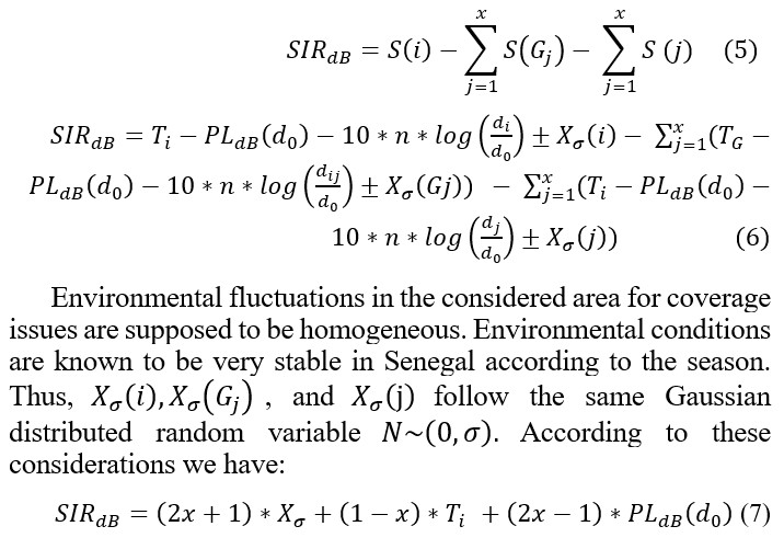
Environmental fluctuations in the considered area for coverage issues are supposed to be homogeneous. Environmental conditions are known to be very stable in Senegal according to the season. Thus, , and follow the same Gaussian distributed random variable According to these considerations we have:
where j represents the number of interfering gateways for a given gateway i.
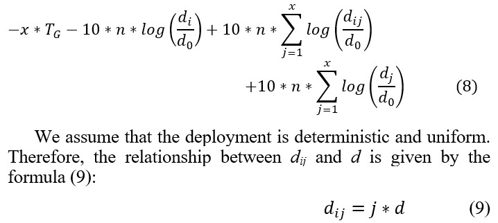
In addition, for all the nodes j associated with the same gateway, we can affirm that the distance dj is almost equivalent to the distance dij . Thus, from equation (8) we have:
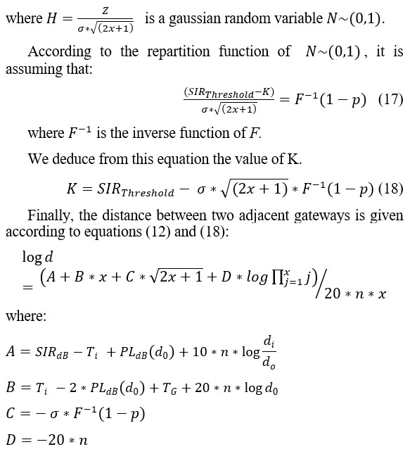
The mathematical analysis makes it possible to unambiguously determine the optimal deployment of gateway nodes minimizing interference. This allows us to define a reusable deployment pattern to cover a large agricultural area. The choice of pattern takes into account the characteristics of the environment considered as environmental fluctuations due to rainfall, the nature of the soil, etc. The pattern is defined as the set formed by a gateway Gi and the interfering gateway nodes Gj which guarantee a given reception threshold. The minimum distance d as a function of the size of the pattern is proposed in the following.
Evaluation is done according to the conditions described in [33]. It should be noted that in Senegal the work on smart agriculture is currently in a purely experimental phase [34,35]. Therefore, the work does not focus on the propagation model. Hence the choice of parameters for an environment similar to that of Senegal such as in Lebanon’s environment. Path loss parameters are shown in Table 2.
Table 2: The path loss parameters
| Parameters | Values |
| Tip | 14 dB |
| TGj | 20 dB |
| di | 2000 m |
| n | 4,179 |
| σ | 7,2 dB |
| Reception probability | 0.9 |
| PLdb(d0) | 102,86 |
It is shown according to the paper [22] that for a spreading factor of 12 and a reception rate of around, the ISR threshold is equal to 6 dB.
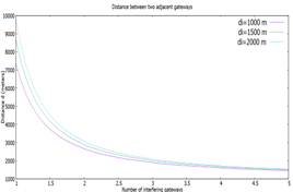
Figure 6: Number of interfering gateways as a function of distance
Figure 6 represents the minimal distance between two adjacent gateways. It shows the influence of the distance between an end device node and its gateway on the deployment. Indeed, it shows the maximum number of interfering gateways for a given distance di. The curve shows that the number of interfering gateways is inversely proportional to the distance. Indeed, when the distance is excellent, the interference is less and therefore the interference can be limited to 1 gateway. On the other hand, when the distance is reduced (less than 3000 m), the interferences are very significant. In this case, the number of interferents increases without exceeding a limit of 5. It should also be noted that the minimum distance does not exceed the defined distance di.
In the specific case of the rice fields of Casamance, it is preferable to minimize the equipment that makes up the architecture because of the presence of water around the fields. Therefore, it is more advisable to choose the deployment of gateways over long distances (example d = 6Kms).
7. Conclusions and future work
Smart agriculture is seen today as a very important lever for winning the challenge of food self-sufficiency in a world where resources such as water are becoming increasingly scarce. Indeed, the new techniques of irrigation, monitoring of soil quality, of temperature make it possible to improve productivity and maintain cultivable soils. In the particular case of Casamance in Senegal, the practice of smart agriculture must take into account the very dense rainfall in this environment. This implies the choice of the most appropriate sensors and wireless communication technology. Moreover, it is necessary to have an optimal deployment of the sensors to have good coverage of the zone. This induces the study of a network architecture that ensures this purpose.
A new LoRa network architecture based on the classical one is presented in this paper. This architecture combining short and long-range LoRa radio links make it possible to carry out smart agriculture in rural areas, particularly in the southern area of Senegal. It focuses on the specific case of the rice field for irrigation system purposes. An analytical study on the deployment helps us to define a model of deployment of the nodes particularly the gateways. This study is based on factors such as the SIR, the reception probability, the distance between nodes, etc. In future work, we first plan to simulate the network in Omnet++ to confirm the analytical study. This involves conducting a performance study in terms of throughput, end-to-end delay, and energy to analyze the advantages and limits of the model. Then, it is about deploying LoRa sensors and gateways in a real environment.
- P. Sethi, S.R. Sarangi, “Internet of Things: Architectures, Protocols, and Applications,” Journal of Electrical and Computer Engineering, 2017, 1–25, 2017, doi:10.1155/2017/9324035.
- L. Atzori, A. Iera, G. Morabito, “The Internet of Things: A survey,” Computer Networks, 54(15), 2787–2805, 2010, doi:10.1016/j.comnet.2010.05.010.
- K.N. Swaroop, K. Chandu, R. Gorrepotu, S. Deb, “A health monitoring system for vital signs using IoT,” Internet of Things, 5, 116–129, 2019, doi:10.1016/j.iot.2019.01.004.
- D.S.R. Krishnan, S.C. Gupta, T. Choudhury, “An IoT based Patient Health Monitoring System,” in 2018 International Conference on Advances in Computing and Communication Engineering (ICACCE), IEEE: 01–07, 2018, doi:10.1109/ICACCE.2018.8441708.
- T.A. Khoa, M.M. Man, T.-Y. Nguyen, V. Nguyen, N.H. Nam, “Smart Agriculture Using IoT Multi-Sensors: A Novel Watering Management System,” Journal of Sensor and Actuator Networks, 8(3), 45, 2019, doi:10.3390/jsan8030045.
- M.R.M. Kassim, “IoT Applications in Smart Agriculture: Issues and Challenges,” in 2020 IEEE Conference on Open Systems (ICOS), IEEE: 19–24, 2020, doi:10.1109/ICOS50156.2020.9293672.
- D. Thakur, Y. Kumar, S. Vijendra, “Smart Irrigation and Intrusions Detection in Agricultural Fields Using I.o.T.,” Procedia Computer Science, 167, 154–162, 2020, doi:10.1016/j.procs.2020.03.193.
- D.M. Andeme Bikoro, S. Fosso Wamba, R.M. Etoua, “Effective Contribution of Internet of Things (IoT) in Smart Agriculture: State of Art,” Lecture Notes of the Institute for Computer Sciences, Social-Informatics and Telecommunications Engineering, LNICST, 443 LNICST, 219–233, 2022, doi:10.1007/978-3-031-06374-9_14.
- M. Cicioğlu, A. Çalhan, “Smart agriculture with internet of things in cornfields,” Computers & Electrical Engineering, 90, 106982, 2021, doi:10.1016/J.COMPELECENG.2021.106982.
- G.S. Nagaraja, A.B. Soppimath, T. Soumya, A. Abhinith, “IoT Based Smart Agriculture Management System,” in 2019 4th International Conference on Computational Systems and Information Technology for Sustainable Solution (CSITSS), IEEE: 1–5, 2019, doi:10.1109/CSITSS47250.2019.9031025.
- J.P.S. Sundaram, W. Du, Z. Zhao, “A Survey on LoRa Networking: Research Problems, Current Solutions and Open Issues,” 2019.
- J. Haxhibeqiri, E. de Poorter, I. Moerman, J. Hoebeke, “A Survey of LoRaWAN for IoT: From Technology to Application,” Sensors, 18(11), 3995, 2018, doi:10.3390/s18113995.
- E.A. Abioye, M.S.Z. Abidin, M.S.A. Mahmud, S. Buyamin, M.H.I. Ishak, M.K.I.A. Rahman, A.O. Otuoze, P. Onotu, M.S.A. Ramli, “A review on monitoring and advanced control strategies for precision irrigation,” Computers and Electronics in Agriculture, 173, 2020, doi:10.1016/j.compag.2020.105441.
- L. García, L. Parra, J.M. Jimenez, J. Lloret, P. Lorenz, “IoT-based smart irrigation systems: An overview on the recent trends on sensors and iot systems for irrigation in precision agriculture,” Sensors (Switzerland), 20(4), 2020, doi:10.3390/S20041042.
- R.K. Kodali, M.S. Kuthada, Y.K. Yogi Borra, “LoRa Based Smart Irrigation System,” in 2018 4th International Conference on Computing Communication and Automation (ICCCA), IEEE: 1–5, 2018, doi:10.1109/CCAA.2018.8777583.
- V. Saiz-Rubio, F. Rovira-Más, “From Smart Farming towards Agriculture 5.0: A Review on Crop Data Management,” Agronomy, 10(2), 207, 2020, doi:10.3390/agronomy10020207.
- P. Sumathi, R. Subramanian, V. Karthikeyan, S. Karthik, “Retracted: Soil monitoring and evaluation system using EDL‐ASQE: Enhanced deep learning model for IoT smart agriculture network,” International Journal of Communication Systems, 34(11), 2021, doi:10.1002/dac.4859.
- K.A. Patil, N.R. Kale, “A model for smart agriculture using IoT,” in 2016 International Conference on Global Trends in Signal Processing, Information Computing and Communication (ICGTSPICC), IEEE: 543–545, 2016, doi:10.1109/ICGTSPICC.2016.7955360.
- E.M. Hasiri, A. Asniati, M.A. Suryawan, R. Rasmuin, “The Implementation of Smart Farming Application Based on the Microcontroller and Automatic Sprinkler Irrigation System of Agricultural Land,” Advances in Science, Technology and Engineering Systems Journal, 5(2), 174–179, 2020, doi:10.25046/aj050222.
- H. Klaina, I.P. Guembe, P. Lopez-Iturri, M.Á. Campo-Bescós, L. Azpilicueta, O. Aghzout, A.V. Alejos, F. Falcone, “Analysis of low power wide area network wireless technologies in smart agriculture for large-scale farm monitoring and tractor communications,” Measurement, 187, 110231, 2022, doi:10.1016/J.MEASUREMENT.2021.110231.
- S.J. Suji Prasad, M. Thangatamilan, M. Suresh, H. Panchal, C.A. Rajan, C. Sagana, B. Gunapriya, A. Sharma, T. Panchal, K.K. Sadasivuni, “An efficient LoRa-based smart agriculture management and monitoring system using wireless sensor networks,” International Journal of Ambient Energy, 1–4, 2021, doi:10.1080/01430750.2021.1953591.
- T.A. Khoa, M.M. Man, T.-Y. Nguyen, V. Nguyen, N.H. Nam, “Smart Agriculture Using IoT Multi-Sensors: A Novel Watering Management System,” Journal of Sensor and Actuator Networks, 8(3), 45, 2019, doi:10.3390/jsan8030045.
- G. Ferre, F. Rivet, R. Tajan, E. Kerherve, “Design and Deployment of an IoT Network Based on LoRa,” in 2017 27th EAEEIE Annual Conference (EAEEIE), IEEE: 1–5, 2017, doi:10.1109/EAEEIE.2017.8768583.
- P.J. Basford, F.M.J. Bulot, M. Apetroaie-Cristea, S.J. Cox, S.J. Ossont, “LoRaWAN for Smart City IoT Deployments: A Long Term Evaluation,” Sensors, 20(3), 648, 2020, doi:10.3390/s20030648.
- L. Irio, R. Oliveira, “Modeling the Interference caused to a LoRaWAN Gateway due to Uplink Transmissions,” in 2019 Eleventh International Conference on Ubiquitous and Future Networks (ICUFN), IEEE: 336–340, 2019, doi:10.1109/ICUFN.2019.8806142.
- B. Reynders, S. Pollin, “Chirp spread spectrum as a modulation technique for long range communication,” in 2016 Symposium on Communications and Vehicular Technologies (SCVT), IEEE: 1–5, 2016, doi:10.1109/SCVT.2016.7797659.
- G. Baruffa, L. Rugini, V. Mecarelli, L. Germani, F. Frescura, “Coded LoRa Performance in Wireless Channels,” in 2019 IEEE 30th Annual International Symposium on Personal, Indoor and Mobile Radio Communications (PIMRC), IEEE: 1–6, 2019, doi:10.1109/PIMRC.2019.8904298.
- V.R. Stoynov, V.K. Poulkov, Z. v. Valkova-Jarvis, “Interference Management in LoRaWANs — Overview and Simulation Study,” in 2018 Advances in Wireless and Optical Communications (RTUWO), IEEE: 251–256, 2018, doi:10.1109/RTUWO.2018.8587904.
- T. Elshabrawy, J. Robert, “Analysis of BER and Coverage Performance of LoRa Modulation under Same Spreading Factor Interference,” in 2018 IEEE 29th Annual International Symposium on Personal, Indoor and Mobile Radio Communications (PIMRC), IEEE: 1–6, 2018, doi:10.1109/PIMRC.2018.8581011.
- G. Ferre, A. Giremus, “LoRa Physical Layer Principle and Performance Analysis,” in 2018 25th IEEE International Conference on Electronics, Circuits and Systems (ICECS), IEEE: 65–68, 2018, doi:10.1109/ICECS.2018.8617880.
- J.-T. Lim, Y. Han, “Spreading Factor Allocation for Massive Connectivity in LoRa Systems,” IEEE Communications Letters, 22(4), 800–803, 2018, doi:10.1109/LCOMM.2018.2797274.
- G.P. Efthymoglou, P.S. Bithas, A.G. Kanatas, “Exact SNR and SIR analysis in Poisson wireless networks,” Electronics Letters, 53(5), 356–358, 2017, doi:10.1049/el.2016.2378.
- R. el Chall, S. Lahoud, M. el Helou, “LoRaWAN Network: Radio Propagation Models and Performance Evaluation in Various Environments in Lebanon,” IEEE Internet of Things Journal, 6(2), 2366–2378, 2019, doi:10.1109/JIOT.2019.2906838.
- C.S.M. Babou, B.O. Sane, I. Diane, I. Niang, “Home Edge Computing Architecture for Smart and Sustainable Agriculture and Breeding,” in Proceedings of the 2nd International Conference on Networking, Information Systems & Security – NISS19, ACM Press, New York, New York, USA: 1–7, 2019, doi:10.1145/3320326.3320377.
- L. Ndiaye, K. Gueye, S. Ouya, “Proposal for an alert and monitoring solution based on the SIP and IoT protocol: the case of agriculture,” in The 4th International Conference on Networking, Information Systems amp Security., ACM, New York, NY, USA: 1–6, 2021, doi:10.1145/3454127.3457617.