Technical Aspects and Social Science Expertise to Support Safe and Secure Handling of Autonomous Railway Systems
 , Andrea Prochazka 1, Elke Szalai 2, Sebastian Chlup 3, Anton Fraunschiel 4
Adv. Sci. Technol. Eng. Syst. J. 7(6), 283–294 (2022);
 DOI: 10.25046/aj070632
In recent years the development of autonomous vehicles has increased tremendously and a variety of methodologies had been applied to make them more safe and secure. This work shows a multilevel approach combining Failure Mode, Effects and Criticality Analysis of an autonomous railway system with sociological and technical aspects to support safe operations and human-machine interactions in the field of autonomous railway systems. This approach includes all relevant technical components, as well as the assessment of measures for a safety process based on the Failure Mode, Effects and Criticality Analysis. We applied the Persona- Roberta model to assess safety aspects at the interface between humans and machines and applied both results to establish training materials. The results provide answers to questions about the avoidance of technical errors, discussions on security and safety aspects and shows organizational development tools for accident prevention. In the future the created knowledge will be used to improve trust in digital solutions and Cyber-Physical Systems.
1 Introduction
This paper is an extension of work originally presented in 2021 at the 5th International Conference on System Reliability and Safety (ICSRS) [1]. In the paper entitled ”Knowledge Based Training De- rived from Risk Evaluation Concerning Failure Mode, Effects and Criticality Analysis in Autonomous Railway Systems” the following four topics have been discussed:
- Railway vehicles, autonomous systems, safety & security, risk mitigation
- Development of a component meta-model ( Figure 1)
- Risk evaluation with Failure Mode Effects and Criticality Analysis (FMECA) focused on technical and social aspects and the combination of these aspects to find solutions for minimizing risks
- Finding a solution to the issues of interaction between autonomous systems, Cyber-Physical Systems (CPS) and humans (Persona–Roberta model)
In thier work [2] looked at a meta-model that would assist the development of Cyber-Physical Systems (CPS) which are to be used to manage and control autonomous train systems on auxiliary railway lines in a safe and secure manner. In doing so, they discovered that most meta-models do not meet the particular requirements of the railway domain, particularly when focusing on the integration of the combination between safety and security issues. Our meta-model, which was developed in response to these findings, incorporates a wide range of particular technological and sociocultural factors as well as their interoperability. It serves as the foundation for the study described in this publication. In the extension for this article, the authors would like to discuss aspects of the research process in the interaction between CPS and people working at an operating site regarding safety and security aspects. This also concerns tools for developing trust and trustworthiness in technology and CPS. Therefore, we developed training materials for different target groups, which are working with and within these systems in different positions. For that, it is important to understand, which person has tacit knowledge and can decide actions and which person can only operate along a guideline.
The authors have been conducting research on the topic of autonomous rail-bound vehicles on branch lines in Linz, Austria for over a total of 18 months. The overall project duration of the research project in which the presented research had been conducted was three years from August 2019- January 2021. Through direct access to the practical use of the planned autonomous system, safety aspects have been comprehensively discussed in the project. The authors overall objective is to connect social, technical and legal issues in an integrative way to achieve greater safety and security for humans and machines in autonomous systems.
Based on the data and research reports on technology acceptance and social issues in technology social research, a mixed methods approach was chosen, which helps to illuminate the research object with different methods according to the grounded theory [3]. Mixed methods research is often used in the behavioural, health, and so- cial sciences, especially in multidisciplinary settings and complex situational or societal research. This approach is chosen when data is to be collected using different methods. These can be quantitative and qualitative methods, but they are not used side by side or in parallel, but triangulated to produce results. In the present research project, this approach was the right one, as the research question asks for social and technical aspects and interdisciplinary cooperation was used. Therefore, desk research methods were used to evaluate existing literature along categories of technical and social aspects. Based on the results, discussions were held with experts to generate information for the development of the Persona-Roberta model indicators. Furthermore, with this basis, the existing FMECA was extended to include social aspects. The aim of all these steps was to extend the error correction measures on the technical side to include social correction measures. These are the training materials developed from these steps, which in turn were fed from the tacit knowledge of the people responsible for the operation. In this way, a knowledge cycle was created to move from person-controlled rail-based operation to safe autonomous operation.
Doing this we set the following research objectives:
- Implementing social aspects to support the technical development of an autonomous railway system
- Extension of FMECA with design thinking methods
- Development of training concepts and materials to ensure safe and secure operation for humans and machines interacting with rail-bond vehicles
The rest of the paper is structured as follows. In section 2, relevant related scientific literature on the subjects of autonomous railway vehicles, FMECA and training materials and the Persona- Roberta model are presented. The next section 3 presents all objects used in the FMECA, failure mitigation and improvement opportunities in detail, followed by section 4, where training materials derived from the FMECA are presented. In the conclusion, a summary of the research is given and further research is presented.
2 Related Works
2.1 Autonomous Railway Vehicles
Recent technological improvements have led to more focus on the sector of autonomous vehicles. A variety of technologies are contributing to the progress of projects and research in this fields. When considering autonomous driving, roughly three parts, scene recognition, path planning and vehicle control are required [4]. While the first demands localization, object-detection and object-tracking algorithms, the second uses motion and mission planning. The latter makes use of the motion planner and uses path following. All these components use algorithms to aid and enable autonomous driving for vehicles. Regarding the railway sector, a variety of projects have targeted different aspects of autonomous driving for trains and railway vehicles, such as self-driving trains, autonomous train sys- tems and others. Technologies such as the Internet of Things (IoT), AI, Dedicated Short-Range Communication (DSRC) and Positive Train Control (PTC) all enhance the autonomy of railway vehicles. Various work in the field of autonomous railway vehicles have been done in academia already. Speed scheduling for autonomous rail- way vehicle control systems has been researched using a variety of algorithms such as Neural Network [5], Neuro-Fuzzy systems [6], fuzzy interference system [7]. They propose the need for a secure and safe operation of trains enabled by an AI supported system.
Autonomous railway vehicles can be classified based on four Grades of Automation (GoA) [8]. GoA 1 describes controlled man- ual operations where the driver manually drives the train, opens passenger doors, etc. and is supported by a safety system, the Automatic Train Protection (ATP). GoA 2 includes automatic braking and change of rail tracks, etc. but is still dependent upon a driver. GoA 3 represents trains that operate autonomously but need a driver to attend the train, be onboard and take control in case of an emergency. GoA 4, however, are fully autonomous trains without a driver present. A lot of progress has been done in recent years regarding fully autonomous train systems. Rio Tinto, for examples, uses fully automated trains for its iron-ore freights in Pilbara, Australia. The system, called AutoHaul, operates 50 automated and unmanned trains on a 1500 km railroad, reducing time and costs [9].
In a recent work by [10], autonomous maintenance technologies for localisation and navigation have been presented. Respective technologies, such as on-board sensors, like Inertia Measurement Unit (IMU), tachometers, satellite-based position systems and cam- eras are used to identify the exact location, speed and other factors regarding the trains. In a further step, these technologies can be used for autonomous movement and driving of a train, as expressed by [11], for monitoring passengers and goods as well as trains and other systems. These advancements and technologies, however, bring up further issues regarding safety of humans, passengers in particular, and other objects involved that are interacting in one way or the other with an automated/driverless railway vehicle or corresponding control system. These factors need to be addressed appropriately.
2.2 Failure Mode Effects and Criticality Analysis
The Failure Mode and Effects Analysis (FMEA) is a formalized method that enables the identification of possible failures of compo- nents of an overall system and their further classification based on root causes, failure modes and estimation of risk [12]. Therefore, errors are identified for specific objects of a system and technical effects for this error are described as well as possible reasons for the respective errors. In this article, we present results from a special form, the Failure Mode Effects and Criticality Analysis
(FMECA)that additionally includes a Criticality Analysis. This is represented in the risk priority number (RPN) assigned to each risk for each failure. The RPN is calculated by multiplying severity, occurrence and detection rates for each failure [13], [14].
When looking at scientific research in the field, FMECA has been applied in various areas of railroad systems. For example, Catelani et al. [15] conducted an FMECA assessment for heating, ventilation and air conditioning (HVAC) systems of transportation railway systems. They identified the main criticalities and in a fur- ther step applied a new analytical method to identify a threshold risk value. In their study, [16] used an FMECA on the passenger door systems of railroad rolling stock. Additionally, they looked at inexpensive and reliable criteria in that context and developed a mileage-based preventive maintenance program to lessen failure recurrence.
To find an optimum FMECA process and methodology for railroad systems, [17] have done a structured evaluation of various FMEA approaches. As a result, they contrasted the approaches and traits of the FMECA standards MIL-1629a, SAE-J1739, and IEC- 60812 for use in the automotive, electronics, and military industries, respectively. They discovered that each was deficient in certain components necessary for a comprehensive approach to FMECA for train systems, and, as a result they combined elements of fail- ure modes (SAE-J1739), maintenance analysis (MIL-1629a), and localization of impacts (IEC-60812). These examples demonstrate that research in this area is ongoing, however it appears that there are no studies that examine the social implications of risk reduction and error correction in FMECA. This gave us even more motivation to pursue improved FMECA research in the railway industry and incorporating social measures for error correction.
2.3 Training materials and the Persona-Roberta Model
The chosen models of error analysis (FMECA) and the developed Persona–Roberta model make it clear that it is relevant and impor- tant to seriously work on these levels in order to create meaningful error correction measures, but also training and work documents for the executing employees.
It is known from models of technology assessment that an aware- ness of the possible consequences of a technical implementation, but also of a human action, must be comprehensively created. These models are complemented by technology acceptance approaches that help to convey assessment processes or develop teaching tools for the people concerned. Acceptance is the subject of numerous scientific studies. One of the best-known models for explaining acceptance is the Technology Acceptance Model (TAM) [18]. This model describes the acceptance of new technology in IT. Technol- ogy interacts strongly with the product, the application of knowl- edge and with the development of a product. Both terms structure technology developments and the access of people to these devel- opments. This approach is the basis for the further development of the Persona-Roberta model chosen in the research project, because as the error analysis and the development of the error correction measures (FMECA) show, in addition to technical knowledge, it also – or above all – requires trust in the new technology.
Knowledge about acceptance requires knowledge about the at- titudes of the counterpart and in order to make these visible, the
aforementioned model of Persona(s) was chosen. Interactions be- tween people and technology (human-machine) require an exact understanding of precisely these interactions. For this purpose, the Persona(s) model can be extended to the Robertas, which makes interfaces and interactions between these two systems visible. In the present use case – in the case of self-propelled rail-bound vehicles in connection with industrial production, this existing knowledge of the employees must be recognised, used and further developed in order to ensure safe – in the sense of error- and accident-free – operations. In the research project, established models were further developed and combined by the various disciplines represented in order to find customised solutions. The combination of FMECA theory, TAM-models and the Persona–Roberta model allowed the derivation of proposals for the development of communication tools and training materials for the staff concerned.
”In the future, there will be a co-existence between humans and machines. ( ) The relationship (…) will therefore be crucial for the experience” [19]. This pattern is also about trust in the machine (sensors, camera, IoT, …) , about knowing how it works and about the impact of the interaction with his Persona as an expert for au- tonomous railways. The development of the Persona(s) supported the research process and made it possible to draw on the generated ideas of possible expectations and fears. This is important, because one result of fear could be errors or wrong reactions in the event of a malfunction, which must be avoided. For this reason, the Persona model was expanded and shows in detail the possible interactions between human and machines. The development was based on the Persona-Robona model by Lewrick and Leifer [20] and makes it possible to describe and understand relationships between the systems that are responsible for a smooth process. At the same time, required knowledge modules, expertise and communication requirements become visible, which can subsequently be addressed through training measures [20].
3 Results of Failure Mode Effects and Crit- icality Analysis
In this section, the FMECA objects identified in the research project [1] are presented and their respective RPNs and technical, as well as socio-technical error corrective measures are displayed.
The research concentrated on auxiliary railway lines, while es- pecially focusing on aspects of security and safety related to this form of railway transportation. In this matter, the authors present the autonomous railway vehicle as an exemplary extract from the proposed autonomous railway system. Figure 1 shows the compo- nents of the respective component of an autonomous railway vehicle. For each component of the meta-model the conducted FMECA is presented, including technological as well as socio-technical error correction measures.
3.1 Camera
When it comes to retrieving information about surroundings, cameras represent one of the most common technologies. They repre- sent a component that is comparatively cheap but has a significant impact on the perception of the surroundings. In this sense we
are not talking about a simple camera but a component capable of processing image data in order to detect and identify potential ob- stacles such moving humans or static objects. In combination with other components a camera can contribute to the decision making within an automated vehicle and therefore, has a vital impact on the safety[21].
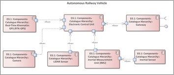
Figure 1: Subcomponents of the autonomous railway vehicle as a component of the meta-model
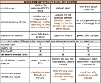
Figure 2: Camera object from FMECA
For a graphical depiction of the result of the FMECA for the object camera see Figure 2. When we connect the camera compo- nent to the FMECA, we identified the following possible errors: a defect on the camera itself, an unclean lens or an error in the power connection. The possible technical effects of the error defect on the camera itself are, firstly, that obstacles are not recognized, secondly, pictures are not displayed correctly, or lastly, that there are no ac- tion possibilities in case of missing pictures. Possible reasons for the above-mentioned errors are accidents caused by fallen objects, deposits on the lens or damages on the power cables. Regarding the estimation of the potential danger as well as possible measures for error prevention, we evaluate the error possibilities with the metrics occurrence (O), severity (S) and detection (D). For each of them we developed a metric corresponding to the potential occurrences of er- rors, as well as to the risk of severity and detection in several rounds
based on the respective expert knowledge of the entire project team. The RPN determined was assigned to three categories with the help of an ABC analysis. The first category is reserved for RPNs between 0 and 299, where the risk is assessed as low and will be accepted. The second category is for RPNs between 300 and 749, where the risk is assessed as medium and, thus, taking measures to omit the failure mode is recommended. The third category is for RPN from 750 to the maximum possible RPN of 1000, the risk is assessed as high and, thus, assessed that an action is necessary, since on this level people could be in danger [1]. Doing this we receive the RPN for each scenario. In the shown case of the camera, we receive the RPN 240 for ”obstacles are not recognized” caused by a ”defect on the camera itself”, the RPN 56 for ”pictures are not displayed cor- rectly” caused by an ”unclean lens” and the RPN 180 for ”no action possibilities in case of missing pictures” caused by an ”error in the power connection”. For the high-risk areas identified in this way, troubleshooting measures will be developed in a separate next step. For all possible errors listed in the FMECA, measures have also been taken to reduce the cause of errors within the system. These measures are divided into technical and sociological measures [1]. For the technical corrective measure, we determine tasks to protect the camera and/or lens to eliminate the possibility of a defect of the camera or lens. To avoid the possible errors induced by unclean lenses we can clean the lens and/or use self-cleaning lenses and/or a built-in redundancy by using a second camera. To avoid an error in the power connection we focus on the opportunities of alternative ways and areas for the installation, as well as a safer installation of the power chords and/or implementing a redundant power supply. As socio-technical corrective measures we determine the following actions to increase the safety level of the object camera. Continuous interaction between Persona(s) and Roberta(s) to detect possible defects on the camera and/or lens as soon as possible.
3.2 Real Time Kinematics Global Positioning System
Global Navigation Satellite Systems (GNSS) offer various ways of positioning solutions. One of which is standalone Global Po- sitioning System (GPS). It utilizes signals retrieved from a radio link to calculate the current position [22]. However, standalone GPS provides an accuracy of only 2-5 metres [23] and therefore does not represent the up-to-date best solution when it comes to automating vehicles. Consequently, other solutions to determine the position more accurately were invented. With Differential GPS (D-GPS) a more precise position can be calculated. By adding a reference station whose position is known, an additional stationary point can be added to the calculation [24]. Thus, the moving object receives information from the satellites as well as the reference sta- tion which enables a precision of 0.3-0.8 meters [23]. The currently most advanced version of GNSS based position detection is Real Time Kinematics (RTK). They are based on the same principles as D-GPS but involve sophisticated computations and formulas during the course of processing the data. With RTK accuracies of 1-5 centimetres can be achieved [23].
For a graphical depiction of the result of the FMECA for the ob- ject Real Time Kinematics Global Positioning System see Figure 3. When we connect the Real Time Kinematics RTK-GPS component to the FMECA, we identified the following possible errors: a loss of the power connection to the RTK-GPS and a loss of the possibility to connect to the reference station.
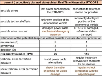
Figure 3: RTK object from FMECA
The possible technical effects of the error loss of the power connection are, firstly, that the position of the autonomous vehicle is unknown and, secondly, incorrectly displayed positions of the au- tonomous vehicle. Possible reasons for the above-mentioned errors are damages on the power cables and/or damages on the reference station. Regarding the estimation of the potential danger as well as possible measures for error prevention we evaluate the error possi- bilities with the metrics occurrence (O), severity (S) and detection (D). For each of them we developed a metric corresponding to the potential occurrences of errors as well as to the risk of severity and detection. Doing this we received the RPN 96 for damages on the power cables and the RPN 144 for damages on the reference station.
3.3 Light Detection and Ranging Sensor
In the past Light Detection and Ranging (LiDAR) was utilized in areas such as measuring ground topography, vegetation canopies or predicting forest stand structures [25]. Nowadays the application field of LiDAR has adapted towards automation and autonomous vehicles. With LiDAR one can measure the distance to targets which might be potential obstacles. This is done by directing a laser onto surfaces within the environment and measure the time-of-flight, i.e. the time needed for the reflected light to return to the light source [26]. Moreover, the change in wavelength is considered. This way, the environment can be scanned and a digital representation of the surroundings is generated. Especially, when thinking about autonomous systems such as robots, vehicles or railway vehicles it becomes apparent that static information and manual measurements are not sufficient, as an up-to-date representation of the current surrounding of the automated entity is required. Therefore, LiDAR takes care of remote sensing in terms of obstacle detection by scanning the environment for autonomous vehicles and other objects and plays an essential role in automatically navigating through a given path.
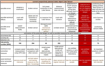
Figure 4: LiDAR object from FMECA
For a graphical depiction of the result of the FMECA for the object Light Detection and Ranging Sensor see Figure 4. When we connect the Lidar Sensor to the FMECA, we identify the following possible errors: obstacle is overlooked, broken sensor, lost power connection to the LiDAR sensor, distance measurement does not work, EMERGENCY STOP sensors trigger at the wrong time, al- though there is no danger, EMERGENCY STOP sensors are not triggered in the event of danger and positioning at the parking po- sition, blast furnace or steel mill does not work at the wrong time. The possible technical effects of these errors are: crash with ob- stacle, Sensor values are not forwarded or forwarded incorrectly, no response from LiDAR sensor, crash with obstacle, availability is limited and ,thus, autonomous operation is difficult, danger to persons and damage to property possible and end of journey unclear. Regarding the estimation of the potential danger as well as possible measures for error prevention we evaluate the error possibilities with the metrics occurrence (O), severity (S) and detection (D). For each of them we developed a metric corresponding to the potential occurrences of errors as well as to the risk of severity and detection. Doing this we received the RPNs from left to right RPN 160, RPN 294, RPN 48, RPN 252, RPN 96, RPN 810 and RPN 72. For the
technical corrective measures, we determine tasks to protect the LiDAR Sensor. To avoid the ”possible error obstacle is overlooked” we compare speed measurement using GPS data, plausibility checks and comparison with other sensors to avoid broken sensors and a safer installation of the power connections to avoid errors in the power connection to the LiDAR Sensor. To avoid ”the possible error distance measurement does not work” we install sensors alternatively and/or install self-cleaning capabilities for the LiDAR unit (e.g. ultrasound). To avoid ”EMERGENCY STOP sensors trigger at the wrong time, although there is no danger” as well as ”EMERGENCY STOP sensors are not triggered in the event of danger”, we use certified systems and/or carry out certification, redundancy and avoid that ”positioning at the parking position, blast furnace or steel mill does not work at the wrong time” we install two separate LiDAR sensors for important positions. As socio-technical corrective measures we determine the following actions to increase the safety level of the system Lidar Sensor. In case of ”obstacle is overlooked” the Persona(s) must not intervene, in case of ”broken sensor” limiting values should be set and training measure on this table/knowledge, in case of ”lost power connection to the LiDAR Sensor” one has to check the cable sheathing for visible damage. In case of ”distance measurement does not work” the sensors must be cleaned at regular intervals. In case of ”EMERGENCY STOP sensors trigger at the wrong time, although there is no danger” and ”EMERGENCY STOP sensors are not triggered in the event of danger” a measure is to train the operating people and in case of ”positioning at the parking position, blast furnace or steel mill does not work at the wrong time” regular test intervals should be integrated.
3.4 Inertial Measurement Unit (IMU)
Inertial Measurement Units (IMU) are utilized in a variety of to- day’s technical systems. Most commonly, IMUs are applied in the automotive and aerospace sector. But even smartphones rely on the technology to measure velocity, acceleration, rotation and gravita- tional force [27]. An IMU relies mainly on two types of sensors. An accelerometer capable of measuring the inertial acceleration and a gyroscope aimed at detecting the angular rotation. Alongside a given starting location e.g. retrieved via D-GPS or Real Time Kinematics GPS an IMU can give information about a vehicle’s position and even orientation. For this, linear and angular accelera- tion measurements are used to improve the precision of the location determination. Some newer IMUs even integrate a magnetometer to further boost the gyroscope measurements [28] , [29]. Moreover, IMUs in contrast to cameras, LiDARs or other sensing components need no exposure to the outside and can be mounted at any part of the vehicle and are not affected by outside conditions. [29]. Con- sequently, they can aid in a precise localization of an autonomous railway vehicle, especially in areas where other types of sensors reach their limits e.g. in tunnels where the GPS signal is lost.
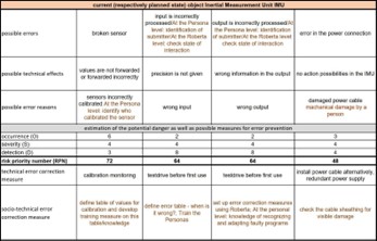
Figure 5: Inertial Measurement Unit object from FMECA
For a graphical depiction of the result of the FMECA for the ob- ject Inertial Measurement Unit see Figure 5. When we connect the Inertial Measurement Unit IMU to the FMECA, we identified the following errors: ”broken sensor”, ”incorrectly proceeded input”, ”incorrectly proceeded output” and ”errors in the power connection”. The possible technical effects of the error ”broken sensor” are that values are not forwarded or forwarded incorrectly. The technical
effect of the error ”incorrectly proceeded input” is that the needed precision is not given. The technical effect of the error ”incorrectly proceeded output” is that wrong information is used for further ac- tions and the technical effect for ”error in the power connection” is that there is no action possible for the IMU. Possible reasons for the above-mentioned errors are: incorrectly calibrated sensors, wrong inputs, wrong outputs and damages on the power cable. Regarding the estimation of the potential danger as well as possible measures for error prevention we evaluate the error possibilities with the met- rics occurrence (O), severity (S) and detection (D). For each of them we developed a metric corresponding to the potential occurrences of errors as well as to the risk of severity and detection. Doing this we received the RPNs from left to right in Figure 5 RPN 72, RPN 64, RPN 64 and RPN 48. As technical corrective measures we determine tasks to protect the IMU to eliminate the possibility of failure. In this case we determine the calibration of the monitors to avoid broken sensors, test drives before first usage, to avoid incor- rect inputs as well as incorrect outputs and alternative ways for the installation, as well as a safer installation of the power connections. As socio-technical corrective measures we determine the following actions to increase the safety level of the system IMU. To avoid errors in the calibration we define ”table of values for calibration and develop training measure on this table/knowledge”. To avoid incorrect inputs, we identified the measure ”define error table and train the Persona(s)”. To avoid incorrect outputs, we set up error correction measures using Robertas. At the Persona level we train the knowledge of recognizing and adapting faulty programs and to avoid errors in the power connection, we implement continuous cable sheathing checking.
3.5 Inertial Sensor
For a graphical depiction of the result of the FMECA for the object Inertial Sensor see Figure 6. When we connect the Inertial Sensor to the FMECA, we identified the following possible errors: ”no data output”, ”a broken sensor”, ”incorrect values”, ”errors in the power connection”.
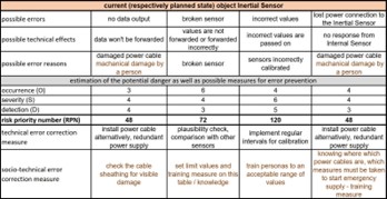
Figure 6: Inertial Sensor object from FMECA
The possible technical effects of the error ”no data output” is that data won’t be forwarded. The technical effect of the error ”broken sensor” is that values are not forwarded or forwarded incorrectly. The technical effect of the error ”incorrect values” is that incorrect values are passed on and the technical effect of an error in the power
connection is that there is no response from the Inertial Sensor. Possible reasons for the above-mentioned errors are damages in the cables, broken sensors, incorrectly calibrated sensors, and damages on the power cable. Regarding the estimation of the potential danger as well as possible measures for error prevention we evaluate the error possibilities with the metrics occurrence (O), severity (S) and detection (D). For each of them we developed a metric correspond- ing to the potential occurrences of errors as well as to the risk of severity and detection. Doing this we received the RPNs from left to right in Figure 6 RPN 48, RPN 72, RPN 120 and RPN 48. As the technical corrective measure, we determine tasks to protect the Inertial Sensor to eliminate the possibility of failure. In this case we determine an alternative installation of the cables to avoid the error of ”no data output”, plausibility checks and comparison with other sensors to avoid ”broken sensor”. To avoid ”incorrect values”, we implement regular intervals for calibration and to avoid errors in the power connection we implement a safer installation of the power connections. As socio-technical corrective measures we determine the following actions to increase the safety level of the system Iner- tial Sensor. To avoid errors in the power connection we implement continuous cable sheathing checking. To avoid errors caused by a broken sensor we set limits of values and develop training measures on this table/knowledge. To avoid incorrect values, we define an acceptable range of values and train the Persona(s). To avoid errors in the power connection we implement trainings to identify and know the exact locations of power cables and which measures must be taken to start emergency power supply.
3.6 Gateway
A Gateway or network gateway is used to establish communication between networks. It represents a hardware component capable of addressing a host potentially unknown to the user and enables the exchange of data with various other components. In our use case, we require a gateway for the automated railway vehicle to communicate with the infrastructure, provide information as well as receive information in terms of controls and reactions. Gateways find multiple applications in networking and in the area of IoT [30], [31].
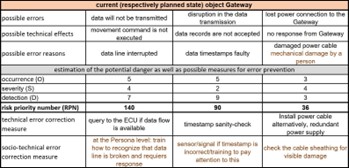
Figure 7: Gateway object from FMECA
For a graphical depiction of the result of the FMECA for the object Gateway see Figure 7. When we connect the Gateway to the FMECA, we identified the following possible errors: ”data will not be transmitted”, ”distribution in the data transmission”, ”errors in
the power connection”. The possible technical effects of the error ”data will not be transmitted” are that movement commands are not executed. The technical effects of a distribution in the data transmission are that data records are not accepted and the technical effect of an error in the power connection is that that there is no re- sponse from the Gateway. Possible reasons for the above-mentioned errors are interruptions in the data line, faulty data timestamps and damages on the power cables. Regarding the estimation of the potential danger as well as possible measures for error prevention we evaluate the error possibilities with the metrics occurrence (O), severity (S) and detection (D). For each of them we developed a metric corresponding to the potential occurrences of errors as well as to the risk of severity and detection. Doing this we received the RPNs from left to right in Figure 7 of RPN 140, RPN 90 and RPN 36. As the technical corrective measure, we determine tasks to protect the Gateway to eliminate the possibility of failure. To avoid the possible error that data will not be transmitted, we implement a query to the ECU if data flow is available. To avoid a distribution in the data transmission, we implement timestamp sanity checks and to avoid errors in the power connection we implement continuous cable sheathing checking. As socio-technical corrective measures we determine the following actions to increase the safety level of the system Gateway. To avoid errors that data will not be transmit- ted we train the employees on how to recognize that data lines are broken and require a response. To avoid a distribution in the data transmission we implement alerts that show when timestamps are incorrect and train the employees to pay attention to these alerts. To avoid errors in the power connection, we implement continuous cable sheathing checking.
3.7 Electronic Control Unit
For a graphical depiction of the result of the FMECA for the object camera see Figure 8. When we connect the Electronic Control Unit (ECU) to the FMECA, we identified as possible errors a mechanical damage, a big in the control software, a software update error, and errors in the power connection.
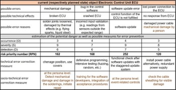
Figure 8: Electronic Control Unit object from FMECA
The possible technical effects of the error mechanical damage are broken ECU. The technical effect of the error bug in the control software is a crashed ECU. The technical effect of a software update error is that the ECU cannot fulfil their control function and the technical effect of an error in the power connection is that there is no
response from the ECU. Possible reasons for the above-mentioned errors are loosened solder joints, incorrect input validations, wrong software updates and damages on the power cable. Regarding the estimation of the potential danger as well as possible measures for error prevention we evaluate the error possibilities with the metrics occurrence (O), severity (S) and detection (D). For each of them we developed a metric corresponding to the potential occurrences of errors as well as to the risk of severity and detection. Doing this we received the RPNs from left to right RPN 162, RPN 168, RPN 252 and RPN 120. For the technical corrective measure, we determine tasks to protect the ECU to eliminate the possibility of failure. In this case we determine a safer installation for the ECU and/or the usage of covers, defensive programming and intensive testing, a functional check after software updates with the staggered- update-system and a safer installation of the power connections. As socio-technical corrective measures we determine the following actions to increase the safety level of the system ECU. To avoid errors in the calibration we define table of values for calibration and develop training measures on this table/knowledge. To avoid mechanical damages, we define scheduled controlling and train the Persona(s). To avoid a crashed ECU, we implement trainings for the software developers and integrate of acceptance procedures. To avoid software update errors, we implement event-related controls at the Persona level and to avoid errors in the power connection we implement continuous cable sheathing checking.
3.8 Combining multiple sensor data for safety au- tonomous driving
In the previous chapter multiple sensor types were pointed out. Cam- eras, RTK GPS , LiDAR and IMUs were picked as an example to clarify the need of different types of sensors for localization and obstacle detection. Especially, in autonomous/automated (railway) vehicles sensors represent a vital factor when it comes to perceiv- ing surroundings and position detection. From a safety perspective there must also be a redundancy within these components in case of failure. The components must be either present multiple times or another component can take over in terms of failure. However, this also requires ways to identify failures, on the one hand, and to be able to correct them, on the other hand. Therefore, data from multiple sensors must be combined in order to enable thorough decision making. This is also called sensor fusion [32]. With sensor fusion data from multiple sensors can be analysed and incorporated. In our case information is exchanged with the infrastructure over a gateway. Thus, yielding additional data for the sensor fusion to compute. Moreover, discrepancies between sensors can be identi- fied and corrected. This way, information from contradicting data sources can be identified and data from various sources enables precise decision making.
4 Development of training materials
4.1 Persona-Roberta model
The interaction between humans and machines is illustrated by the Persona-Roberta model in Figure 9). It shows, what interactions
there are between the systems that have to work together in auto- mated operation and do flawlessly so as not to put anyone in danger. On one side are Personas that act as a model and in the analysis of the possible social factors that can act in the cooperation. These include social categories that characterise a person, an employee, such as his or her age and language, but also his or her professional experience or position in the company. All these factors have an influence on their actions and their understanding of the overall system, but also on their willingness to learn and develop, which is necessary as technical and organisational systems evolve. On the other hand, the Roberta model helps to understand which dif- ferent technical systems are used, which knowledge is required to operate and understand them and which errors can also occur. This knowledge about the technical processes and systems is necessary to recognise errors and to prevent them before they cause damage. In this field of the model, we have to link it with the FMECA to find solutions for a safe operation at any time. These insights help to connect the measures for error elimination with concrete human knowledge and to take appropriate measures. Critical errors can only be eliminated on a conditional technical basis with suggestions in FMECA. This modelled mapping can be used for the develop- ment of error correction measures related to the FMECA as well as for the development of training measures. These should make particular reference to the interfaces and interactions between these systems and design training measures accordingly.
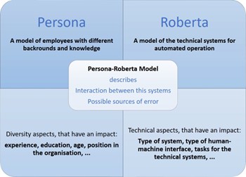
Figure 9: Persona-Roberta model
4.2 On-the-job training
Based the theoretical groundwork presented in Section 2 and expert discussions with the industry partners, a training concept was de- veloped that empowers people to gain confidence in the machine and to make the right decisions based on their experience. For the development of the first draft of the training concept, learning the- ory principles and organisational learning as well as the generated error correction measures from the FMECA were used. Thus, a sound safety concept is a basis of the training concept that helps to comply with safety standards. Furthermore, responsibilities are clearly addressed to persons who bring in existing experience, but who can also be trained specifically for new requirements.
In order to be able to develop training measures as precisely as possible, it needs:
- Document analysis of work instructions
- Overview of safety guidelines
- Analysis of current training folders
- Interviews or participatory observations
It is also clear that in system-theoretical adult education or systemic-constructivist didactics, no lectures and conversions [33] should happen, but to put self-direction and the learning of the indi- vidual person as knowledge carrier in the centre. This is also about the possibility of co-developing training measures [34].
It can also be recommended that training should include a mix of formal and informal teaching steps and that ”learning on-the-job” should be established. In any case, any documents produced should be continuously revised in order to incorporate technical changes/ further developments, but also to bring new teaching methods and knowledge of the knowledge bearers into training documents. Building on the knowledge management approach to learning or- ganisations, the following initial concept of training or planned documentation was developed. Engel and Koch [35] have bridged organisational development and organisational learning with the field of enterprises as For-Profit-Organisations and their highly struc- tured and determined process for learning environments. Faulstich [36] calls for the necessity of addressing formal and informal power as an aspect of advanced internal trainings, which also seems rel- evant when addressing possible resistance to new technologies by employees. Kirchner [37] points out that the organisational identity of an enterprise is also relevant – in our case a self-reference as “innovative”, “participative”, “learning organisation” or “modern”. Research in this area has shown that up to now, the full potential of informal learning processes and tacit knowledge of employees, as well as participative methods have not been tapped by internal trainings.
Identify people who have knowledge and those who need to be trained and create appropriate materials. These have the focus of stimulating learning, learning to solve complex problems together and presenting them through simple language and symbols. On-the- job trainings for employees should be designed in a way that they address their specific worries, needs, state of knowledge and enable them to participate within the design process and to bring in their ideas to reduce risk factors – including oral and written didactic methods as well as thinking-out-loud processes to gain access to implicit and tacit knowledge. Elderly workers or users are often seen as digital migrants and a tackle for implementing new technologies. However, we call for applying ethnographical observations of experienced operators to sustain and involve treasure trove of their experience in the development of new technologies. Thus, a modern understanding of innovation which allows modifications during the process is vital. Technical methods like FMECA should be combined with sociological methods like Design Thinking. For the training settings, management tools are also presented to create an understanding of plan-do-check-act [38].
4.3 Tools and settings for developing the trainings and materials
How do people learn in organisations?
One important point is to use existing tacit knowledge of experi- enced employees and to take it seriously. There are different tools from knowledge management to capture this knowledge. Helpful are: Expert discussions, how-to listens, but also concepts such as micro-articles, which help to prepare knowledge clearly for other people [39]. The selection of interviewees is based on the iden- tified Persona(s) and the concrete contact persons derived from them as well as the work areas identified in the FMECA. Narrative interviews are conducted with these people to help capture their ex- periences and knowledge of the processes and activities. In this way, it becomes clear which activities and actions are currently being carried out and what changes will occur as a result of automated operation. After this acidity the development of basic materials and trainings settings can start. This should be linked with the results of the FMECA to include possible dangerous situations and solutions to solve it.
In general it is important to define and communicate for update intervals, responsible persons and admins, including an annual train- ing plan. This plan must be communicated by the management and the technical experts of the industry partner. All these steps must be linked to the time requirements for updates and many more. In the training documents, documents are continuously developed and simple training settings are set.
The following framework conditions are planned in the research project: The focus is on knowledge in the organisation and a transfer of knowledge. Documents and a handbook will be developed for the training courses with knowledge carriers, which can be continuously developed and adapted to the current technical requirements. The focus of the developed documents will be on using simple language and clear symbols in order to be able to communicate the complex process of self-driving operation to all persons equally. Furthermore, it will be addressed that not all persons need to know everything, but are comprehensively and well trained in their fields of work.
The following learning concepts are used for this purpose: Self- directed learning [40], as this concept considers the individual’s own learning speed and prior knowledge. Basic documents on paper but also on videos are provided and simple tests to check knowledge. In addition to self-directed learning, this teaching concept also allows individual parts of the documents / videos to be easily expanded or exchanged. “The benefits of self-directed learning can be described in an effective manner in terms of the types of learners it develops. The self-directed learners demonstrate a greater awareness in terms of responsibilities.” [40] Beside the self-directed learning concept, a peer-learning concept will be used. In the practice settings, learners practice in tandems. In particular, documentation sheets are filled in and reflected on as examples. Focus on the presentation and explanation of all components and their connections, as well as the possible errors. It is also planned to engage specially trained per- sons (admins), which are responsible for an overview on the whole content and new requirements. The goal of all measures is to train responsibility through learning theoretical expansion! For this pur- pose, a review and adaptation of all created documents is required at least every 12 months when changing the sensor or increasing
knowledge in real operation. Furthermore, it must also be a matter of discussing planning with staff and checking for understanding. This can happen with small online tests that the person has to do or by independently handling a possible error correction action. This can be documented by the training management with the help of an internship or observation sheet and any retraining can be proposed. In this way, the entire team can develop further.
For the development of initial materials and didactic concepts for in-company training in relation to new work processes through auto- mated rail-bound driving on the premises, the basic work was used in order to make custom-fit proposals from a socio-scientific-technical point of view. These are, as shown: FMECA – Persona-Roberta model – Building blocks of knowledge management – Foundations of organisational learning.
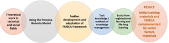
Figure 10: Combination of tools for training material development
As Figure 10 illustrates, there is no simple implementation guide, but there are many tools and methods that can be used to ensure smooth and flawless operation of autonomous rail-bound vehicles in the industry. The tools shown can be used to further develop and use them according to one’s own requirements. This is achieved through the cooperation of different disciplines that contribute their technical and social expertise.
These tools and methods were supplemented by the basics of adult education and e-learning, since parts of the planned further ed- ucation are to function online and with the concept of self-directed learning in the future. All documents are to be developed and reviewed in consultation with the Human Resources, Technical De- velopment and Hazard Management departments. It will also be clearly worked out who is responsible for the final design of all documents and course units, who is responsible for the individual training parts, who adapts and modernises them accordingly if some- thing changes in the sequence of events. It can be assumed that this technology will continue to develop and, therefore, documents, as well as tools and concepts, must be constantly updated. These aspects point to the future and also show the challenges of future research work. It is clear that concepts of adult education and a managing diversity concept [41] should be taken as a basis. People with their knowledge and social characteristics are thus perceived in their entirety as a relevant resource and integrated into knowledge processes. This also closes the circle to knowledge management, which had been used in the research project in particular to raise the explicit knowledge of the employees. How do adults learn? There is no one-size-fits-all answer, but there are frameworks that help to design one’s own learning environment in order to be able to communicate new technologies that bring about changes in work processes. The needs of adults, which can motivate them to learn, must be as precisely as possible and relate them to the respective needs (qualification profiles, etc.) [42]
If we combine these starting points with the aspects of organi- sational learning, managing diversity theory and knowledge man- agement that have already been worked out, they provide sufficient orientation for the selection of didactic methods and the targeted preparation of content and learning materials. Once again, refer- ence should be made to the diversity of learners in an industrial company and to the requirements of clear languages, unambiguous images and small snippets of information that will make it possible to organise the interaction between man and machine with the most well-founded knowledge possible in a safe and error-free manner. A regular evaluation of the success of the training courses with regard to possible incidents complements the overall approach of integrating social and socio-scientific aspects into technical training.
5 Conclusion and further research
The proposed set of tools and models can contribute to more ap- propriate training materials for humans interacting with machines, in the area of autonomous railway vehicles. Especially, the ex- tended FMECA participates and provides a holistic approach to what a railway operating system should look like and shows which requirements, influences and interfaces must be considered. Ad- ditionally, it is an effective technique to spot security as well as safety concerns at a point where planned systems and human actors interact at the very beginning of the design process. However, the descriptions of the subcomponents of the component autonomous railway vehicle in section 3, indicates a strong relationship between the technical and sociological error correction measures. Regarding the estimation of the potential danger as well as possible measures for error prevention we evaluated the error possibilities with the metrics occurrence (O), severity (S) and detection (D). For each of them, a metric was developed that is corresponding to the potential occurrences of errors as well as to the risk of severity and detection in several rounds based on the knowledge of the entire project team. A multitude of tools and models are then implemented to identify and develop adequate training materials. These are based on the- oretical work in technical and social fields, the Persona-Roberta model, as a model focusing on interaction between humans and ma- chines, tacit knowledge and methods of knowledge management as well as basics of organisational and life-long learning. We propose that together these tools will help and enhance developing more adequate training materials for the autonomous railway sector. In a further step, these materials should then be generated based on the proceedings that have been described and applied to a genuine context of an autonomous railway system.
The novelty of the research and the article lies in the combination of the different research methods and models, which complement each other and combine technical and social issues. It is well known from knowledge management and organizational development that the introduction of new technical processes that bring innovation to operations and processes requires knowledge about the people who will be affected by them. Therefore, research questions such as ”What makes an organizational culture that produces technical and social innovations?” but also ”How does the use of the tacit knowledge of the employees succeed?” For that the research team used methods from organizational learning including aspects of
safety and security and of knowledge management. To stick so- cial and technical aspects together the method of “personas” from design thinking processes was extended with the technical aspects
– “Roberta”. Furthermore, the model of [43] for organizational learning was included.
In the research projects as well as in this article, it could be shown that it is relevant and important to be aware of technical expert knowledge. And besides there must also be knowledge about social factors and social negotiation processes in an organisation, which have an effect on the introduction and operation of new tech- nical systems. It can be stated that interdisciplinary cooperation can deepen the processing of the interaction between machines and humans. The use and further development of known instruments such as the FMECA and models such as the Persona-Roberta model enables a structured derivation of possible training measures and contents. The existing knowledge of (long-term) employees must be used as a basis in order to be able to integrate informal experiential knowledge specifically into the selection of the learning setting and the preparation of the materials. Existing hazard plans in the organi- sations and technical knowledge complement the development and help to establish safe operations. In summary, it can be said that this contribution shows where research and development must go in the future, in order to further develop autonomous rail-bound driving on company premises, both technically and socially. The presented research results have already been implmented in teachings in a variety of departments at the University of Applied Scienes Burgen- land. And the research partners further suggest on implementing the results in upcoming research projects in the field of autonomous railway systems and others with focus on sustainable nationwide mobilty. We further suggest that the implementation of social as- pects can aid in developing such a system and support the further mitigation of failures by applying and developing adequate training materials.
Conflict of Interest
The authors declare no conflict of interest.
Acknowledgment
Research leading to these results has received funding from the project BESTE-AB, funded by the Austrian Re- search Promotion Agency (FFG), coordinated by the Austrian Insti- tute of Technology.
- C. Gnauer, A. Prochazka, E. Szalai, S. Chlup, S. Luimpo¨ A. Fraunschiel, C. Schmittner, “Knowledge-Based Training Derived from Risk Evaluation Concerning Failure Mode, Effects and Criticality Analysis in Autonomous Railway Systems,” in 2021 5th International Conference on System Reliability and Safety (ICSRS), 47–52, 2021, doi:10.1109/ICSRS53853.2021.9660726.
- D. Hofbauer, C. Schmittner, M. Brandstetter, M. Tauber, “Autonomous CPS Mobility Securely Designed,” in 2019 IEEE 20th International Symposium on ”A World of Wireless, Mobile and Multimedia Networks” (WoWMoM), 1–6, 2019, doi:10.1109/WoWMoM.2019.8793050.
- D. Walker, F. Myrick, “Grounded theory: An exploration of process and procedure,” Qualitative health research, 16(4), 547–559, 2006, doi: 10.1177/ 1049732305285972.
- S. Kato, E. Takeuchi, Y. Ishiguro, Y. Ninomiya, K. Takeda, T. Hamada, “An open approach to autonomous vehicles,” IEEE Micro, 35(6), 60–68, 2015.
- N. Anwar, M. S. Khan, K. Ahmed, A. Ahmad, A. Athar, “Speed scheduling of autonomous railway vehicle control system using ANN,” International Journal of Scientific & Engineering Research, 2(6), 1–6, 2011.
- A. Ahmad, M. S. Khan, K. Ahmed, N. Anwar, A. Athar, “Speed Scheduling of Autonomous Railway Vehicle Control System using Neuro-Fuzzy System,” International Journal of Scientific and Engineering Research, 2(6), 272–277, 2011.
- A. Ahmad, M. S. Khan, K. Ahmed, N. Anwar, U. Farooq, “FIS Based Speed Scheduling System of Autonomous Railway Vehicle,” International Journal of Scientific and Engineering Research, 2(6), 299–304, 2011.
- P. Singh, M. A. Dulebenets, J. Pasha, E. D. S. Gonzalez, Y.-Y. Lau, R. Kamp- mann, “Deployment of autonomous trains in rail transportation: Current trends and existing challenges,” IEEE Access, 9, 91427–91461, 2021.
- “Rise of the machines: Rio Tinto breaks new ground with AutoHaul,” 2019.
- M. Rahimi, H. Liu, I. D. Cardenas, A. Starr, A. Hall, R. Anderson, “A Review on Technologies for Localisation and Navigation in Autonomous Railway Maintenance Systems,” Sensors, 22(11), 2022, doi:10.3390/s22114185.
- R. Lagay, G. M. Adell, “The autonomous train: A game changer for the railways industry,” in 2018 16th international conference on intelligent transportation systems telecommunications (ITST), 1–5, IEEE, 2018, doi: 10.1109/ITST.2018.8566728.
- M. Shafiee, F. Dinmohammadi, “An FMEA-based risk assessment approach for wind turbine systems: a comparative study of onshore and offshore,” Energies, 7(2), 619–642, 2014, doi:10.3390/en7020619.
- L. S. Lipol, J. Haq, “Risk analysis method: FMEA/FMECA in the organizations,” International Journal of Basic & Applied Sciences, 11(5), 74–82, 2011.
- J. Singh, S. Singh, A. Singh, “Distribution transformer failure modes, effects and criticality analysis (FMECA),” Engineering Failure Analysis, 99, 180–191, 2019, doi:https://doi.org/10.1016/j.engfailanal.2019.02.014.
- M. Catelani, L. Ciani, D. Galar, G. Guidi, S. Matucci, G. Patrizi, “FMECA assessment for railway safety-critical systems investigating a new risk threshold method,” IEEE Access, 9, 86243–86253, 2021, doi:10.1109/ACCESS.2021. 3088948.
- F. Dinmohammadi, B. Alkali, M. Shafiee, C. Be´renguer, A. Labib, “Risk evaluation of railway rolling stock failures using FMECA technique: a case study of passenger door system,” Urban Rail Transit, 2(3), 128–145, 2016, doi:10.1007/s40864-016-0043-z.
- J. Kim, H. Jeong, J. Park, “Development of the FMECA process and analysis methodology for railroad systems,” International Journal of Automotive Technology, 10(6), 753–759, 2009.
- F. D. Davis, “Perceived usefulness, perceived ease of use, and user acceptance of information technology,” MIS Quarterly, 319–340, 1989, doi: 10.2307/249008.
- M. Lewrick, P. Link, L. Leifer, N. Langensand, Das Design Thinking Playbook: mit traditionellen, aktuellen und zuku¨nftigen Erfolgsfaktoren, Vahlen, 2018.
- M. Lewrick, P. Link, L. Leifer, A. Schmidt, Das Design Thinking Toolbook: Die besten Werkzeuge & Methoden, Franz Vahlen, 2019.
- D. J. Yeong, G. Velasco-Hernandez, J. Barry, J. Walsh, “Sensor and Sensor Fusion Technology in Autonomous Vehicles: A Review,” Sensors, 21(6), 2021, doi:10.3390/s21062140.
- Y. Feng, J. Wang, “GPS RTK Performance Characteristics and Analysis,” Jour- nal of Global Positioning Systems, 7, 2008, doi:10.5081/jgps.7.1.1.
- “What is the Difference Between RTK & DGPS?” 2019.
- F. Van Diggelen, “GPS and GPS+ GLONASS RTK,” in Proceedings of the 10th International Technical Meeting of the Satellite Division of The Institute of Navigation (ION GPS 1997), 139–144, 1997.
- N. Mehendale, S. Neoge, “Review on Lidar Technology,” 2020, doi:10.2139/ssrn.3604309.
- M. A. Lefsky, W. B. Cohen, G. G. Parker, D. J. Harding, “Lidar Remote Sens- ing for Ecosystem Studies: Lidar, an emerging remote sensing technology that directly measures the three-dimensional distribution of plant canopies, can accurately estimate vegetation structural attributes and should be of particular interest to forest, landscape, and global ecologists,” BioScience, 52(1), 19–30, 2002, doi:10.1641/0006-3568(2002)052[0019:LRSFES]2.0.CO;2.
- “What is IMU?” 2021.
- N. Ahmad, R. A. R. Ghazilla, N. M. Khairi, V. Kasi, “Reviews on Various Inertial Measurement Unit (IMU) Sensor Applications,” International Journal of Signal Processing Systems, 256–262, 2013, doi:10.12720/ijsps.1.2.256-262.
- “Inertial Measurement Units for Localisation and Navigation of Autonomous Vehicles,” 2019.
- C. P. Kruger, A. M. Abu-Mahfouz, G. P. Hancke, “Rapid prototyping of a wireless sensor network gateway for the internet of things using off-the-shelf components,” in 2015 IEEE International Conference on Industrial Technology (ICIT), 1926–1931, IEEE, 2015, doi:10.1109/ICIT.2015.7125378.
- R. He, B. Ai, G. Wang, K. Guan, Z. Zhong, A. F. Molisch, C. Briso- Rodriguez, C. P. Oestges, “High-speed railway communications: From GSM-R to LTE-R,” Ieee vehIcular technology magazIne, 11(3), 49–58, 2016, doi: 10.1109/MVT.2016.2564446.
- S. Ataei, A. Aghakouchak, M. Marefat, S. Mohammadzadeh, “Sensor fusion of a railway bridge load test using neural networks,” Expert Systems with Applications, 29(3), 678–683, 2005, doi:https://doi.org/10.1016/j.eswa.2005.04.038.
- R. Arnold, H. Siebert, “Konstruktivistische Erwachsenenbildung. Vonder Deutung zur Konstruktion der Wirklichkeit. Baltmannsweiler,” 2003.
- S. Nolda, Einfu¨hrung in die Theorie der Erwachsenenbildung, WBG Darmstadt, 2012.
- N. Engel, S. Koch, “Betrieb als Gegenstand und Ort organisationspa¨dagogis- cher Forschung und Praxis,” in Handbuch Organisationspa¨dagogik, 793–804, Springer, 2018, doi:10.1007/978-3-658-07512-5 77.
- P. Faulstich, Strategien der betrieblichen Weiterbildung: Kompetenz und Or- ganisation, Vahlen, 1998, doi:10.1007/s11618-000-0016-5.
- S. Kirchner, “Organisationsidentita¨t und Unsicherheit,” in Organisation und Unsicherheit, 69–85, Springer, 2015, doi:10.1007/978-3-531-19237-6.
- S. M. Weber, M. Go¨ hlich, A. Schro¨ er, H. Macha, C. Fahrenwald, “Organisa- tion und Partizipation–interdisziplina¨re Verha¨ltnisbestimmungen und organi- sationspa¨dagogische Perspektiven,” in Organisation und Partizipation, 9–28, Springer, 2013, doi:10.1007/978-3-658-00450-7 1.
- A. Mittelmann, Werkzeugkasten Wissensmanagement, BoD–Books on De- mand, 2011.
- R. Kapur, “Significance of Self-Directed Learning,” 2019.
- L. Gardenswartz, A. Rowe, Managing diversity: A complete desk reference and planning guide, McGraw Hill Professional, 1998.
- B. Dewe, K. Feistel, Betriebliche Weiterbildung Materialien in didaktischer und bildungso¨konomischer Perspektive, Franz Steiner Verlag, 2013.
- G. Probst, S. Raub, K. Romhardt, Bausteine des Wissensmanagements, 25–33, Gabler Verlag, Wiesbaden, 2003, doi:10.1007/978-3-322-94790-1 3.