Complete System and Interactions of MMF Harmonics in a Squirrel Cage Induction Motor; Differential Leakage; Analytic Calculation

Adv. Sci. Technol. Eng. Syst. J. 10(4), 20–31 (2025);
 DOI: 10.25046/aj100403
The importance of MMF space harmonics in squirrel-cage induction motors has been recognized in the literature since the beginning. Their details have been analyzed over the years, but only partly systematized. In this article, however, not only the origin and the entire system of that harmonics are described, but also their interaction causing the asynchronous parasitic torques, the synchronous parasitic torques, the radial and tangential magnetic force waves on a systematic way; all of this is done now targeting a complete system, so we include all harmonic phenomena in a single complete equivalent circuit diagram and a single table of the magnetic forces that occur. The so far missing equivalent elements causing the synchronous torques have now been defined. From these, the physical relationship between the phenomena that have often been examined separately will be clearly visible and can be easily calculated. Building on our previous studies, instead of the theoretically infinite number of harmonics hitherto considered, we will describe “exactly” the harmonics that really need to be taken into account, so that the number of harmonics will be much smaller than is usually considered by researchers and designers. Our formulae derived so far are successfully verified with the help of that completed equivalent circuit diagram, supplemented with the so far missing formula for tangential magnetic forces.
1. Introduction
The first complete description of MMF space harmonics occurring in an asynchronous machine is attributed in the literature to [1]. The first (and perhaps the only) series of measurements demonstrating the influence of MMF harmonics on the torque-speed characteristic curve, including the occurrence of synchronous machine phenomena in asynchronous machines, and which series of measurements has been referred to ever since, was carried out by [2]. The effect of MMF harmonics on noise was first systematized by [3]. The books in [4] and [5] not only provided a complete theoretical foundation for the asynchronous machine, becoming the number one fundamental works in the literature by not only defining those harmonics, but also by consistently tracing the effect and calculation of them. In [6], the author explicitly devoted their fundamental work to harmonics. In reality, however, they were, in our view, concerned always with a sub-area of the complete system. This is also true for [7], although he was the first to report the completeness of the MMF and also other harmonics occurring in the air gap of asynchronous machines, partly their interaction, further the sequence and complete procedure of the calculation; however, he did not make the number of harmonics to be taken into account dependent on the number of rotor slots, but thought of it as theoretically infinite.
Although [8] does not directly address their fundamental work to the topic of this article, it provides a theoretical approach to the basic laws of electrical engineering in relation to asynchronous machine, which is indispensable for our topic.
The investigations so far were complete in a certain sense, in a sub-area, indeed, it can always be stated, however, that something was always missing from the completeness, in our opinion the following three things.
The effect of the number of rotor slots was not taken into account, or not so as we believe it should have been. The next reason, which really completes our investigations, is that although previous investigations have recognized that the phenomena occurring in the machine can be modeled with a series of “small” asynchronous motors and “small” synchronous motors representing the effects of the MMF space harmonics, shaft-connected to the “harmonic-free” main motor [6], the small synchronous motors, however, have never been defined. Nor have been recognized the relationship between the small synchronous motors used as models and the radial and tangential magnetic harmonic forces. The final reason is that – in the absence of our formulae – it has not been possible to do more than to specify the frequency of the harmful phenomena (for checking for resonance), so the designer could not define just the slot numbers to be chosen, what he was really looking for but only their opposite, the set of obviously most dangerous slot numbers to be avoided. The latter could only be examined as a way of “avoiding” the so-called slot harmonics.
2. Analytical model
As a model, such a machine is assumed for which the basic formulae for determining the usual resulting space harmonics are valid [6]: infinite relative permeability, two-dimensional fields without considering boundary and end effects, the machine consist of two smooth coaxial cylinders made of magnetic material, the cylinders are separated by the air gap, the conductors of infinitely small cross-section are located in the air gap.
In such a model, the distribution of the excitation current (no-load magnetizing current) flowing in the winding in the air gap will have the same shape as the shape of the magnetic induction or magnetic field, since there will be a linear relationship between the two. Therefore, we often do not talk about excitation (MMF), but about the air gap field and its harmonics. Considering its shape, the MMF curve is always “stepped”, so it is natural that it contains harmonics.
If necessary, in addition to the MMF harmonics, reference will also be made to the magnetic conduction fluctuation harmonics arising due to the stator slot opening, but such case will be indicated explicitly. Time harmonics and harmonics of other origin, such important phenomena as eccentricity and saturation, are not included in the investigation, so that our examination can really concentrate on the MMF space harmonics. The supply voltage is always considered sinusoidal, and the motor is started by connecting it directly to the network (without a frequency converter drive).
The well-known equivalent circuit of the asynchronous machine is valid only for the fundamental harmonic magnetic field, therefore we develop an extended, special equivalent circuit that also takes into account the harmonic fields occurring in the case of the model outlined above.
With the help of our investigation, we explore the generation of parasitic torques during run-up, the generation of radial and tangential forces that cause vibrations and noise during operation, with the aim of understanding of origins and results of different interactions.
Since the derivations as well as the conclusions drawn from the model are based on the fundamental laws of electrical engineering, they do not require validation.
3. MMF harmonics in squirrel cage induction machines
MMF harmonics are given in first step for a 2p=2 pole machine.
Stator MMF harmonics
$$v = 2g \cdot m \pm 1 \tag{1}$$
where m stator phase number
g=0, ±1, ±2, ±3 …
the stator harmonics are independent of the stator slot number.
Rotor MMF harmonics
$$\mu_a = e^{\tfrac{Z_2}{p}} + v_a \tag{2}$$
where Z2 rotor slot number
p pole pair number
e=0, ±1, ±2, ±3 …
νa the stator harmonic that created this rotor harmonic
(Z2/p=m2 rotor phase number)
the rotor harmonics are dependent of the rotor slot number.
Rotor harmonics created by the fundamental harmonic of the stator:
$$\mu_a = e^{\tfrac{Z_2}{p} + 1} \tag{3}$$
This description is suitable for general investigation of the machine – in the case of q1= Z1/2pm = integer i.e. without fraction/subharmonics – including the investigation of parasitic torques – and is therefore usually used there.
In fact, harmonics for the entire perimeter occur in the machine:
on the stator
$$v’ = 1v = 2m \cdot g \cdot p + p \tag{4}$$
on the rotor
$$\mu_a’ = \mu_a p = e^{\tfrac{Z_2}{p}} p + v_a p = e \cdot Z_2 + v_a p \tag{5}$$
Rotor harmonics created by the fundamental harmonic of the stator:
$$\mu_a’ = e \cdot Z_2 + p \tag{6}$$
This notation should be used, for example, for the study of radial and tangential magnetic forces, because this is the only way to interpret the r-order of these force waves.
In addition to MMF (winding) harmonics, in the case of open or semi-closed slots on the stator, magnetic conductivity fluctuation induction harmonics are also generated in the air gap, the order number of which is necessarily determined by the combination of the slot number and the pole pair number.
Stator
$$v_{slot}’ = g_1 \cdot Z_1 + p \tag{7}$$
where g1=±1, (±2, ±3 …),
Rotor
$$\mu_a’ = e_1 \cdot Z_1 + p \tag{8}$$
where e1=±1, (±2, ±3 …).
Going back to stator MMF harmonics (1) let us highlight those of which g=g1∙q1, where q1=Z1/2mp (slot number per phase per pole)
$$\nu = 2mg_1q_1 + 1 = g_1 \cdot 2m \frac{Z_1}{2mp} + 1 = g_1 \cdot \tfrac{Z_1}{p} + 1 = \nu_{slot} \tag{9}$$
$$\nu’_{slot} = \nu_{slot} p = g_1 Z_1 + p \tag{9a}$$
Expressions (7) and (9a) are identical, which means that the stator winding harmonics of order g=g1∙q1 produce an order ν’ along the circumference of the air gap that is equal to the order of the magnetic conductivity fluctuation harmonics. These parts of the whole set of MMF winding harmonics are therefore called slot harmonics. They are also characterized by the fact that their winding factor is the same as the winding factor of the fundamental harmonic ξνslot=ξ1. The term “first (winding) slot harmonic” refers to the order g1=1.
The above implies that the magnetic conduction fluctuation harmonics of open or semi-closed slots are “added” to, but only to, the winding harmonics of order 2mq1±1 and to its multiples g1∙2mq1±1; the two effects cannot then be separated during the operation of the machine. No new harmonics have appeared because of the effect of open slots.
From a comparison of (6) and (8), it is clear that all rotor MMF harmonics generated by the stator fundamental harmonic νa=1 are slot harmonics. The magnetic conduction fluctuation harmonics of the rotor are of minor importance because of the small slot openings.
In the following, the initial definition of ν and μa will remain; if we still turn to using ν’ and μa‘, it will be clearly indicated.
4. The reactance resulting from the MMF harmonics; air-gap leakage – differential leakage
Since the stator MMF is generated from the winding sides placed in the slots, it does not give a pure sinusoidal MMF: the MMF will have spatial harmonics. These harmonic fields are caused by the same stator current, which causes the so-called main/fundamental flux; but the speed of travel of the harmonic fields is not the same as the speed of travel of the main field, but slower being inversely proportional to the order number of that. For this reason, however, they induce a voltage in the winding with a frequency exactly corresponding to the network frequency, i.e. they behave just like a leakage flux. Hence their name, although they are not, is still leakage reactance. And since the phenomenon originates from processes occurring in the air gap, they are called “air-gap” leakage (Luftspaltstreuung) in several languages. The term “differential leakage” just in English comes from the fact that the air-gap leakage fields resulting from the harmonics can be thought of as the difference between the total field and the fundamental field. Since the frequency of the voltage induced in this way is the same as the frequency of the supply voltage, they can be inserted into the usual equivalent circuit diagram in the same way as any other (real) leakage reactance.
The air-gap leakage reactance is defined as the sum of an infinite series:
$$X_{s\sigma_1} = \sigma_1 X_m \tag{10}$$
where
$$\sigma_1 = \sum_{\nu=1}^{\infty} \frac{1}{\nu^2} \frac{\zeta_\nu^2}{\zeta_1^2}$$
This phenomenon also occurs on the rotor, the corresponding reactance can, therefore, be included in the equivalent circuit diagram of the rotor. The air gap leakage fluxes also move slower in inverse proportion to the order number relative to the rotor, so they induce the same frequency in the rotor as the main flux (fundamental harmonic flux) and as the other leakage reactances do, so it is also justified to include them in the equivalent circuit diagram. Definition:
$$X’_{s2\sigma_1} = \sigma_2 X_m \tag{11}$$
where
$$\sigma_2 = \sum \frac{1}{\mu^2}$$
Instead of the inconvenient infinite summation, a formula was developed based on the Görges diagram.
The differential leakage reactance (let us remain with this term from now on) [5] (258)
$$X_{2\sigma} = X_m \cdot \sigma_{2\sigma} \tag{12}$$
where
$$\sigma_{2\sigma} = \frac{1}{\eta_k^2} – 1$$
where
$$\eta_{2,1} = \frac{\sin\!\left(\tfrac{p\pi}{Z_2}\right)}{\tfrac{p\pi}{Z_2}}$$
η2,1 is hardly different from 1: η2,1≈ 1 .
Each harmonic flux of the differential leakage of the stator induces voltage (and current) in the rotor in the same way as the main (fundamental harmonic) flux – in other words, the cage rotor responds to a rotating field of any number of poles, i.e. responds to all MMF harmonic fields – and can therefore be imagined and modelled with small asynchronous machines shaft-connected to the rotor of the harmonic-free main motor. For this reason, it is usual to unfold the differential leakage elements (10) and assign to them one by one a separate small asynchronous machines’ equivalent circuit diagram, electrically in series connection, mechanically in shaft connection, see e.g. [6] p. 110 Figure 41, but anywhere in the literature. These can then be used to explain and calculate the asynchronous parasitic torques and harmonic attenuation.
It has been shown that the leakage reactance of these small harmonic induction machines includes only the differential leakage reactance (of their rotor); this finding is only approximately true for the 5th and 7th harmonics [1], [5], [6], but in order to simplify the physical picture and the calculation, we consider them generally true for the time being.
The rotor differential leakage calculation of the small harmonic asynchronous machines was also developed based on the Görges diagram instead of the infinite series summation.
The differential leakage reactance [5] (268)
$$X_{2\sigma\nu} = X_{m\nu} \cdot \sigma_{2\sigma\nu} \tag{13}$$
where
$$\sigma_{2\sigma\nu} = \frac{1}{\eta_k^2} – 1$$
rotor differential leakage coefficient.
The denominator is the so-called Jordan’s coupling factor. Its definition ([5] 268b):
$$\eta_{\nu a} = \frac{\sin\!\left(\tfrac{\nu p \pi}{Z_2}\right)}{\tfrac{\nu p \pi}{Z_2}} \tag{13a}$$
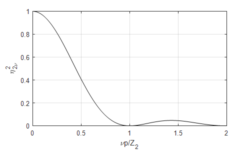
Expression (13a) is plotted on Figure 1. It shows how much the rotor responds to a stator harmonic. A zero or very low value indicates that the rotor does not respond to that harmonic. Then the differential leakage factor will be very high or even infinite ([6] Figure 17. p. 44).
Figure 1 is very difficult to interpret for a daily design work. Therefore, for a better illustration and more in line with the designer’s thinking, we have already transformed this figure in [9]; the range νp/Z2>1 was replaced by zero, since the highest value in this range is only ≈4.5%.
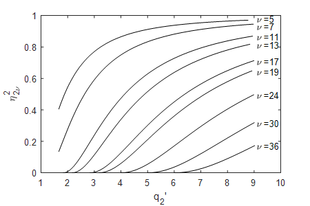
The “physical message” of the figure is the following:
if q2’≤2, the machine does not respond to νa = 11, 13 (being otherwise the first slot harmonics of a stator winding q1=2) and to any harmonics of higher order;
if q2’≤3, the machine does not respond to νa = 17, 19 (being otherwise the first slot harmonics of a stator winding q1=3) and to any harmonics of higher order; and so on.
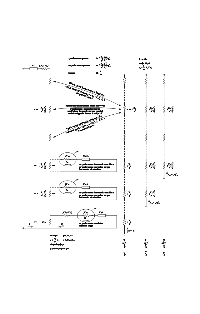
This is the basis for our consideration of how to limit the theoretically infinite number of stator harmonics in the machine to a finite, not even unmanageably large, number of harmonics depending on the number of rotor slots, while still remaining theoretically correct. A first practical implementation of this approach has already been presented, dividing the stator differential leakage components into groups based on their identical properties, in [10] Figure 1. This figure contains an infinite series of differential leakage reactances, represented in the usual columnar manner; but unlike earlier representations no small asynchronous machine is assigned to stator harmonics higher than first slot harmonics. Now they are shown to the left of the current Figure 3, also in a columnar arrangement.
However, we now make a significant addition to the previous equivalent circuit diagrams (e.g. fill in the so far missing elements) by unfolding the differential leakage reactances of the rotor similarly to those of the stator, connected in series, also in a columnar manner, to the right of the fundamental equivalent circuit. The corresponding fluxes are also plotted with the voltage drop across the indicated reactance caused by the rotor fundamental harmonic current.
The fluxes represented by these reactances do not interact with the stator of the main harmonic-free motor. The normal stator does not respond to them, and this is because the normal stator is designed for a single fixed number of poles and would therefore only respond to a rotor current harmonic field of the same number of poles, i.e. μ=1 order. A cage rotor, however, does not produce such a wave; but if it did in rare cases, it would only produce it with a large νa order, [5] p. 153. Therefore, a small circuit like a small asynchronous machine, but pointing from the rotor to the stator, cannot be assigned to it, and cannot interact with it as an asynchronous machine would.
The flux fields represented by the differential leakage reactances of the rotor above, however, do interact with each of the MMF harmonic fields of the stator (and their associated current layer waves) and since they are independent of each other – i.e., neither is excited by the other – the interaction can only be synchronous in nature.
In accordance with the spirit of the figure, and more in accordance with the physical content, the quantities are proposed by the author to be referred with the term “harmonic” in a manner equivalent to the commonly used terms:
- harmonic asynchronous machine / synchronous machine
- harmonic asynchronous / synchronous torque
- harmonic radial/axial forces
- harmonic rotor current I’2ν
The usual term “parasitic” obviously refers to the harmful nature of the torque, the term “small” is not very expressive.
Another important phenomenon is that the spatial harmonics of the rotor’s fundamental current (and also the spatial harmonics of the harmonic rotor currents see later) induce voltages in the stator, but their frequency is not the mains frequency, and therefore they do not appear in the usual voltage equations of
the stator and hence not in the equivalent circuit diagram of an asynchronous machine. For the magnitude and frequency of the stator induced voltage, see Chapter 7 of [11]. Frequency of the induced voltage:
(1+α)∙fnet
where α=eZ2/p∙(1-s)
where s slip of rotor
e positive integer
At a single slip value, at s=1 standstill, however, the frequency of the voltage induced in the stator is exactly the network frequency. Only in this case, the main field and the differential leakage fields cannot be distinguished [5].
Here we note that the cage rotor, however, can generate a wave of order μ=0 for certain numbers of rotor slots with certain νa stator harmonics. In this case, the magnitude of the voltage drop I2ν’∙Xm/μa2∙ξa2/ξ12 in the affected “column” would be infinite, since μ=0 is in the denominator; it is then the harmonic current I2ν‘ of the small asynchronous motor affected by this phenomenon that eventually becomes zero. At the same time, η2ν2 in the expression I2ν’≈-I1η2ν2 will also be zero, so the two approaches give the same result. The physics of the phenomenon is that the wavelength of that stator harmonic is then exactly equal to the rotor’s slot pitch, the induced voltages in the rotor bars are of the same magnitude and direction (zero sequence phenomenon), and thus cannot generate a current in the cage.
The newly applied consideration above (regarding the rotor differential leakage elements of the harmonic-free main machine) will be further extended to the circuits of the small harmonic asynchronous machines, which represent the effect of the stator’s harmonic MMF on the cage: their leakage as differential leakage of that rotor can be unfolded, extracted and plotted separately in the same columnar manner alongside the column of the fundamental circuit. They also interact with the harmonic flux of each MMF in the stator, and form small harmonic synchronous machines in the same way.
Note that an asynchronous circuit ν and a rotor MMF harmonic μ may in some cases have the same order, and both may exist simultaneously. However, the physics of the two are different: one is a real (dependent) rotor current of order ν, the other is an independent harmonic rotor flux field of order μ, and therefore their behavior is different: the one is asynchronous, the other one is synchronous in nature.
All these “of synchronous” interactions of the fields can be perceived in the behavior of the machine as synchronous parasitic torque at well-defined rotor speed (including standstill) and as oscillating torque of the same small synchronous machine in the “out-of-synchronism” status over the rest of run-up speed range and at rated operation (acc. to the author incorrectly called torque ripple), and can also be perceived as radial and tangential magnetic forces over all the speed range (but deeply analyzed usually at no-load and rated load only).
The rotor harmonic fluxes close on the same magnetic paths as those of the stator in the case of the same order number; the calculation of their reactance is, therefore, identical to the calculation of the reactances representing the MMF harmonics of the stator see Figure. 3. With this statement, the small harmonic synchronous motors are defined.
The number of small synchronous machines to be included in the calculation depends on the followings:
- depending on the harmonic wavelength and the size of the (double) air gap, higher harmonics no longer reach the other side of the air gap, i.e. there is no interaction between the stator and rotor at these (high) harmonics; the highest order number of harmonics is “limited” in this way.
- the number of small asynchronous machines created is already limited as a function of the rotor slot number acc. to Figure 2.
Therefore, the number of harmonics to be considered is not infinite, even in theory.
For example, if the stator winding is chorded and the relative rotor slot number is q2‘≤2, then for two reasons, even based on the most rigorous theoretical considerations, it is sufficient to analyze the machine by considering the harmonics of the fundamental rotor current MMF only.
Figure 3 provides a complete map of the harmonic phenomena occurring in a short-circuited asynchronous machine. Every stator harmonic shown on the map is in harmonic relationship with every rotor harmonic. This means a very large number of interactions, although not an infinite number. The limiting phenomena are as follows:
- synchronous parasitic torque can only occur between harmonics of the same order: νb=±μa
- research in this direction has long proven that the order of the radial magnetic force waves to be considered is limited: r= νb’±μa’≤4 (for large machines ≤6) only
- the order of the magnetic force waves to be considered from the perspective of tangential forces has not been defined yet.
Taking this into account – and for the sake of clarity and transparency – Figure 3 shows only one harmonic pair interaction generating synchronous parasitic torque as an example, namely one in which the rotor harmonic happens to be the harmonic generated by the fundamental rotor current MMF (since such rotor harmonics always influence the behavior of the asynchronous machine), and the stator harmonic happens to be of such a high order that a small asynchronous machine no longer belongs to it and is therefore no longer attenuated. For the sake of clarity, we have only presented two interactions that generate radial and tangential magnetic force waves r≠0, which are expected to belong to the “neighboring” harmonics of the harmonic pair generating the synchronous parasitic torque.
As a result, when examining a short-circuited rotor induction motor, while maintaining theoretical rigor, we can limit ourselves to examining a few, but at least a manageable number of well-defined field harmonic interactions (see the studies in [11] Table 9).
Using Figure 3 as a map, we do not need to calculate the total, resulting magnetic field generated in the air gap. For the purposes of this topic, it is sufficient to consider only those harmonics that have a “counterpart on the other side.”
5. Power, torque
The topic was investigated in [10] and [12]. Now, it is elaborated in a different way.
From Figure 3, the powers and torques that occur when the individual harmonics of the stator and rotor interact with each other can also be read.
5.1 Synchronous parasitic torque
From the equations of the synchronous machine the following is chosen to calculate the power of the small synchronous machine:
$$P = \frac{U_s \cdot U_r}{X_d} \tag{14}$$
where
$$U_s = I_1 X_r = I_1 \eta_{2\nu}^2 \frac{X_m}{\nu^2} \frac{\zeta_{5\nu}^2}{\zeta_1^2} \tag{14a}$$
the voltage corresponding to the stator harmonic MMF,
$$U_r = I_1 X_r = I_1 \eta_{2\nu}^2 \frac{X_m}{\mu_a^2} \frac{\zeta_{5\nu}^2}{\zeta_1^2} \tag{14b}$$
the voltage corresponding to the rotor harmonic MMF.
Regarding the harmonics of the rotor fundamental harmonic current;
$$U_r = I_1 X_r = I_1 \frac{X_m}{\mu_a} \tag{15}$$
due to \(\eta_{2,1}^2 \approx 1\) and per definition \(\frac{\zeta_{\nu_a}^2}{\zeta_1^2} = 1\)
Synchronous reactance Xd because good coupling is assumed between stator and rotor harmonic inductances:
$$X_d \approx \sqrt{X_s \cdot X_r} = \sqrt{\frac{X_m}{\nu^2} \frac{\zeta_{5\nu}^2}{\zeta_1^2} \cdot \frac{X_m}{\mu_a^2} \frac{\zeta_{5\nu}^2}{\zeta_1^2}} = \frac{X_m}{\mu_a} \frac{\zeta_{5\nu}}{\zeta_1} \tag{16}$$
where per definition: νb = ±μa
Substituted
$$P = I_1^2 \eta_{2\nu}^2 \frac{X_m}{\mu_a^2} \frac{\zeta_{5\nu}^2}{\zeta_1^2} = I_1^2 \eta_{2\nu}^2 \frac{X_m}{\mu_a^2} \frac{\zeta_{5\nu}^2}{\zeta_1^2} \tag{17}$$
During further transformations, the formula for the synchronous parasitic torque (=oscillating torque) that we derived earlier in a different way, will be obtained and confirmed [12].
5.2 Asynchronous parasitic torque
Power
$$P = U_s I’_{2\nu} = I_1^2 \frac{X_m}{\nu^2} \frac{\zeta_{5\nu}^2}{\zeta_1^2} \eta_{2\nu}^2 \tag{18}$$
During further transformations, the formula for the asynchronous parasitic torque that we derived earlier in a different way will be obtained and confirmed [10].
6. Noise measurements and torque oscillation measurements during start-up
It is a field experience of a commissioning engineer that while starting the motor at rated voltage (unlike starting at strongly reduced voltage in the testroom), significant noise occurs even at very low speeds, and then its frequency increases linearly, while the noise magnitude remains unchanged (apart from the air born noise); see “Tongeraden” [3]. After reaching the breakdown torque, the noise suddenly decreases significantly. It is not customary to measure it, but the frequency of the torque oscillation is obviously the same, and the magnitude of it (not losing sight of the logarithmic nature of the noise) behaves in the same manner as that of the noise. However, the analysis and especially the measurement of the latter is usually omitted from research.
Any measurements made during start-up would require a very significant apparatus, and their practical use is at the same time doubtful. However, there is no doubt that for the sake of a better understanding and especially for the proof of the theory of the processes, taking into account Table 1 see later, such measurement might still not be pointless.
7. The complete system of harmonic tangential and radial magnetic forces and torques occurring in the machine
For a better demonstration and understanding of the physical processes, the complete system of the forces created by the action of the MMF harmonics was included in Table 1 [13]. The table was prepared using the derivations of [8].
Let us see the physical background of the relationship between tangential forces (including synchronous torques) and radial forces. Both the flux density waves and the current layer waves of the stator and rotor resp., as a function of time and location (periphery) are written as follows:
$$b_s = B_s \sin(\omega_s t – p_s x), \quad b_r = B_r \sin(\omega_r t – p_r x – \varphi), \quad a_s = A_s \cos(\omega_s t – p_s x), \quad a_r = A_r \cos(\omega_r t – p_r x – \varphi) \tag{19}$$
where ωs and ωr angular velocities of the fields.
There is the only stipulation that there is a causality relationship between the quantities within the stator as well as within the rotor:
$$a = \text{const} \, \frac{db}{dx} \tag{19a}$$
Otherwise, both stator and rotor quantities can be of any origin; between them there is no forced relationship.
When examining electrical machines in general, it is appropriate to look for the conditions for the formation of a constant torque in time. However, for the purpose of subject research, we are just looking for what happens when the conditions are not met. After all, all combinations occur during the interaction of stator and rotor harmonics.
Table 1: Complete system of radial and tangential harmonic magnetic forces (and torques) created in a squirrel cage induction machine
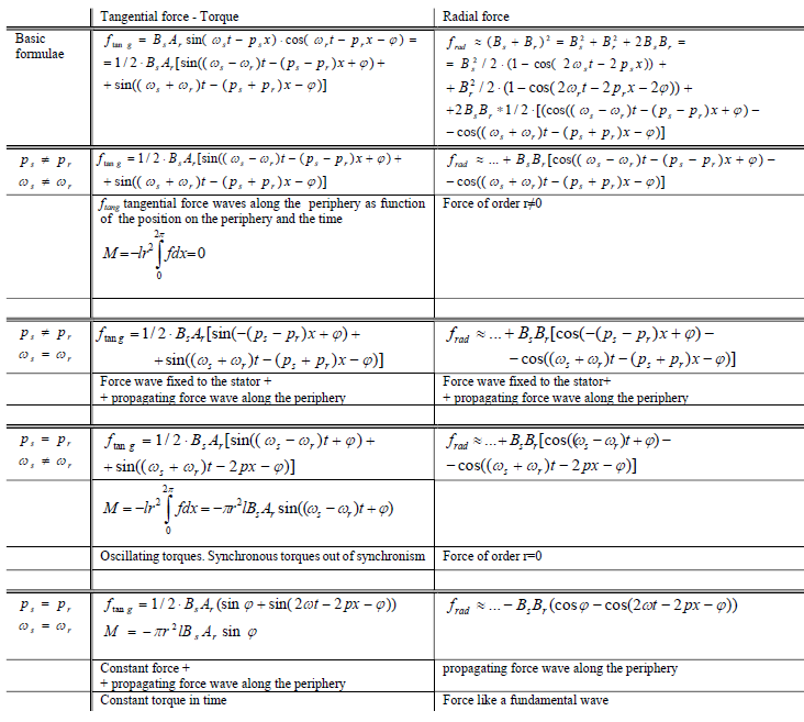
During the examination, we must allow positive or negative value not only for the angular velocity of the fields (the stator field relative to an assumed positive direction, the rotor field relative to the rotor, and the mechanical angular velocity of the rotor also relative to the same positive direction), but also both positive and negative values for the pole pair numbers ps and pr, representing the direction of rotation of the respective rotating harmonic field relative to the assumed positive direction.
The bottom rows of the table show the situation when the conditions for the formation of a constant torque in time are met. This is just the condition for the formation of synchronous parasitic torque. If this is greater than the torque of the main machine considered to be free of harmonics, the main machine “remains stuck”: either at zero speed (standstill) or rotating at a certain speed (not reaching the rated speed).
The rest of the table examines the different possible variants of non-fulfillment of the conditions.
Since both radial and tangential forces will be calculated as products of trigonometric functions, the same transformations always give two force waves of the same magnitude. In reality, of course, their sum gives the resultant force. By studying the mathematical expression of the forces, it can be discovered that the force wave with the lower order r gives the “instantaneous mean value” of the resulting wave.
In practical calculations, only the force wave with the lower order r will be used for calculation, because it is only that being able to make the yoke (and the teeth) vibrate; the other remains out of consideration. It means that in practice we never calculate the real, resultant force, but only its instantaneous mean value (see [3] Fig. 22., [5] Fig. 137.).
We have already identified the phenomenon occurring for three possible variants. Now, the last possible variant is included also in the table in order to make the table complete.
This ωs=ωr , ps ≠ pr newly inserted variant is of something interesting in theory; that if the angular velocities of the stator and rotor fields are exactly the same, that always occurs during run-up or break on a certain rotor speed. Then one of the force waves does not depend on time, this means it is fixed to the stator: this is either the “envelope” curve (if ps and pr have the same sign) or the force with double frequency (if ps and pr have opposite signs), and the other one is the usual traveling / rotating wave. Richter chose just this particular case to demonstrate the creation of the one-sided magnetic pull caused by two induction waves ([5] Kapitel 4. p. 200), if ps ± pr =1. Otherwise, in all cases, both force waves are traveling / rotating waves. A special case is the order number r=0; then the so-called “breathing” force wave cannot be interpreted as a space wave, because it only changes in time, and is constant along the circumference. In reality, a traveling wave with twice the number of poles and approximately twice the frequency also occurs with r=0, but it remains out of consideration in practice.
Regarding Figure 3 and Table 1, note that Table 1 covers the synchronous phenomena while the processes of the harmonic asynchronous machines are governed by the usual asynchronous equivalent circuit diagram.
Before closing this chapter, however, we cannot refrain from making a critical comment regarding [8]. In the derivation, [8] did not impose any restriction on the rotor quantities (“they are of arbitrary origin”). When the conditions of equality of pole number and speed are met, according to [8] (47) p. 47, a constant torque occurs over time and it is referred as asynchronous torque (perhaps in reference to the title of the book). We have adopted this expression in the bottom row of our Table 1 but we have called it synchronous parasitic torque. The resulting torque is asynchronous torque only if the rotor quantities are not of arbitrary origin, but are strictly induced by the stator (according to the equivalent circuit diagram of the asynchronous machine). If they are of any (other) origin, the interaction between the stator and the rotor cannot be other than synchronous torque.
8. Tangential force waves
Tangential harmonic force waves of low order are generated only if νb≠μa (νb’≠μa’). Since these waves cancel each other out along the circumference, i.e. they are not perceived as a torque acting on the shaft, they are generally less considered in research.
The tangential harmonic force wave occurs simultaneously with the radial one. These waves exerts bending loads on the teeth both of the stator as well as of the rotor. In a normal machine design, the magnitude of these force waves does not cause mechanical problems. However, the teeth must be checked for vibration, because the (high frequency) waves can cause the teeth to bend in resonance (even break if poorly designed). For drives with demanding noise emission requirements, this issue should also be addressed; both stator and rotor teeth should be checked, especially during the run-up. Their frequency is of course the same as that of radial magnetic force waves. The tangential harmonic magnetic force is considerably less than the radial one, so the examination is usually omitted. But the mass of the teeth (even with the winding) is also substantially less than the mass of the yoke, so the smaller forces can still cause the teeth to vibrate; this shows that the tangential force must be dealt with the same care.
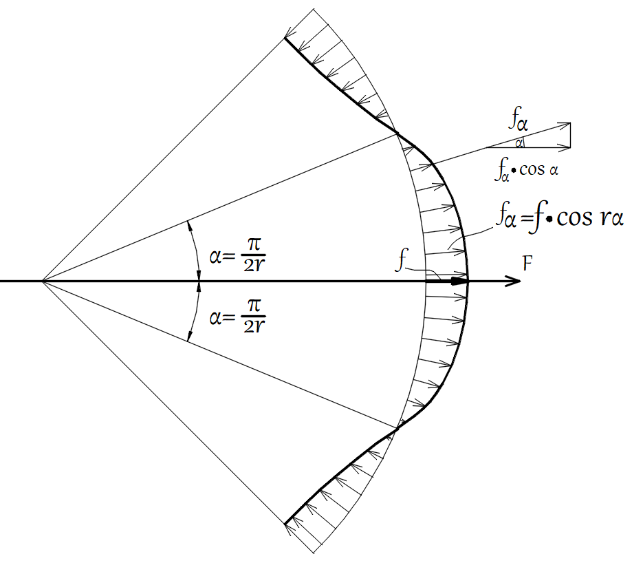
Figure 4 shows an example of the distribution of harmonic radial forces for r=4. Here groups of sinusoidal distributed pulling and (apparently) pushing forces alternate along the periphery. It is known from physics that only tensile forces can arise in the air gap at any point of the circumference, in any operating state. The apparent contradiction has been clarified in the literature (e.g. [3]), so we will not discuss this topic now.
The tangential forces that occur simultaneously also show the same distribution (but offset in angle by π/2r), forming identical groups of forces alternately of positive and of negative direction along the periphery with respect to an assumed positive direction; the resultant torque created by them on the shaft is therefore zero.
8.1 Calculation of tangential magnetic harmonic forces
The calculation is most conveniently started from the formula for radial force [12] (26). From this, the tangential force is calculated using the well-known formula (pμaδ/R) regarding the ratio of tangential to radial forces [3], [7] but [8] is also suitable to apply. Let it be the maximum of a sinusoidal distributed force wave of both forces
$$f_{xmS} = \frac{p \mu_a \delta}{R}, \quad f_{rnd} = \frac{p \mu_a \delta}{R} \cdot \frac{1}{(p_r’ l_r’ \delta)} \left( \frac{m}{2} I_1^2 \frac{X_m}{2 x_d’} \cdot \frac{\zeta_{5\nu}}{\nu p \mu_a} \eta_{2\nu}^2 \frac{1}{\zeta_1^2} \right) \tag{20}$$
where p pole pairs
μa rotor harmonic
δ airgap
R rotor radius
After simplifications, the rotor radius still remains in the denominator. If we multiply by that in order to remove it, we get the local maximum torque
$$m_{max} = R \cdot f_{xmS} = \frac{1}{r_1′ l_r’} \left( \frac{m}{2} I_1^2 \frac{X_m}{2 x_d’} \cdot \frac{\zeta_{5\nu}}{\nu p \mu_a} \eta_{2\nu}^2 \frac{1}{\zeta_1^2} \right) = \frac{W_{mag}}{F_{pole}} \left( \frac{\zeta_{5\nu}}{\nu p \mu_a} \eta_{2\nu}^2 \frac{1}{\zeta_1^2} \right) \tag{21}$$
where Fpole airgap surface of one pole.
However, the formula shows a surprising fact, namely that the elementary harmonic tangential force (torque) does not depend on the rotor harmonic order μa that generates it (note that νb≠μa). This is physically not possible. The explanation is that both of the cited literatures, which studied harmonic flux densities according to their subject (noise), happened to start from the harmonic induction of the rotor to derive the current layer of the rotor for the purpose of calculating the tangential force; hence they arrived at the well-known formula. In [5], however, the expression for the harmonic torque is derived from the harmonic induction of the stator for the purpose of calculating the harmonic current layer of the stator. This approach leads to the following formula
$$m_{max} = \ldots = \frac{W_{mag\nu}}{F_{pole}} \left( \frac{\zeta_{5\nu} \zeta_{\nu a}}{\mu_a} \eta_{2\nu}^2 \frac{1}{\zeta_1^2} \right) \tag{22}$$
which is obviously a contradiction, because Bs∙Ar must be equal to Br ∙As (Table 1).
Deriving the exact formula is laborious. The point is that the wavelengths of the stator and rotor waves are not equal. Therefore, their peaks do not coincide, but are at two different points on the circumference; the maximum of their multiplication falls between the two points. Since only the cases r=νb‘±νa‘=p(νb±μa)≤4 are of interest, νb and μa differ only slightly in the cases to be considered, the development of the exact formula has little practical contribution, but is of theoretical interest only. Therefore, as a compromise, the author proposes the usual geometric mean of the two harmonics. In other words, instead of the formula described so far in the literature, the formula of the ratio is proposed to be
$$f_{tang} = \frac{p \sqrt{\nu_b} \mu_a \delta}{R} – f_{rad} \tag{23}$$
which is obviously closer to the correct theoretical value than that one used so far.
The maximum of the local harmonic magnetic torque created by the maximum tangential magnetic force wave of order r
$$m_{max} = \frac{W_{mag\nu}}{F_{pole}} \left( \frac{\zeta_{5\nu} \zeta_{\nu a}}{\sqrt{\nu_b} \mu_a} \eta_{2\nu_r}^2 \frac{1}{\zeta_1^2} \right) \tag{24}$$
Of course, the starting current must be substituted into (21): I=U/Xs , (where Xs total leakage reactance) since this is when the largest harmonic tangential forces are obtained. With further arrangements, we get back our original equation, [12] (13), again a cross-confirmation of our earlier formula.
Based on Fig. 4, the relative value of the torque created by a half-wave of the tangential forces of order r is proposed as
$$\frac{M_{tang}}{M_{breakdown}} = 2 \frac{X_m}{X_s} \frac{\zeta_{5\nu} \zeta_{\nu a}}{\sqrt{\nu_b} \mu_a} \eta_{2\nu_r}^2 \frac{1}{\zeta_1^2} \cdot \frac{1}{2r} \cdot \frac{2}{\pi} \tag{25}$$
8.2 Consideration of magnetic conduction harmonics due to slot openings
In practice, radial magnetic force waves are usually examined at no-load and at rated load. On this slip of the motor, the magnetic conduction fluctuation harmonics, if any, play a decisive role.
However, the effect of such harmonics is different for synchronous parasitic torques, since they are naturally generated at start-up and low run-up speeds. At these times, the fundamental induction field (being in connection with said fluctuation) is about half the size of the rated one, but the currents generating the MMF harmonics are ≈5times larger, so the role of magnetic conduction fluctuation harmonics is significantly reduced and even ignored. The resulting error may be noticeable, but not so large as to affect the evaluation of the rotor slot number.
However, when considering oscillating torques (so-called torque ripple) in rated operation, which are the result of the operation of the small harmonic synchronous machines in the “out-of-synchronism” state, the magnetic conductivity fluctuation harmonics must also be taken into account (but only if the machine has an open stator slot, i.e. is designed using high-voltage technology), in the same way as for noise calculations [13] Figure 1. In this case, they are strongly dominant – also because their numerical values are not logarithmically “damped” by the dB calculation applied for noise calculations.
8.3 Pole pair numbers to be substituted in Table 1.
For all the radial force waves column and for the tangential force waves
ps= ν’, pr= μa’ pole pair numbers must be calculated.
For the synchronous parasitic torques
ps= ν , pr= μa pole pair numbers must be calculated.
For the oscillating torques during run-up up to breakdown torque slip
ps= ν , pr= μa pole pair numbers must be calculated.
For the oscillating torques around rated speed
ps= ν , pr= μa pole pair numbers must be calculated but
in the case of open stator slots:
the oscillating torque components that arise with the contribution of νslot=2mg1q1+1 , they must be calculated in the same way as found for radial force waves:
ps= ν’, pr= μa’, i.e. taking into account the amplifying effect of the magnetic conduction fluctuation wave.
Note that in the formulae, νb and μa must always be substituted, never νb‘ and μa’.
9. Conclusion
The behavior of the asynchronous motor is determined – for the purpose of our present investigation – by the stator and rotor differential leakage components.
The stator differential leakage components generate harmonic rotor currents in the rotor cage, these currents will create spatial harmonics being also differential leakage components in nature. From subject point of view, therefore, the rotor differential leakage components include all such components created by the fundamental rotor current, as well as those created by the harmonic rotor currents. At the end, each component of the stator differential leakage interacts with each component of the rotor differential leakage. This interaction will occur with any number of rotor slots. The stator and rotor components are independent of each other, and therefore the interactions are of a synchronous machine nature. The entirety of these phenomena determines the behavior of an asynchronous machine: these are the interactions that generate synchronous (harmonic) parasitic torques, radial and tangential harmonic magnetic forces.
The stator differential leakage components interact also with the harmonic rotor currents generated in the squirrel cage by them. Since these harmonic rotor currents depend on (are induced by) the stator differential leakage components, the phenomenon will be asynchronous in nature. These are the interactions that generate the asynchronous parasitic (harmonic) torques. The phenomenon (strongly) depends on the rotor slot number. The effect is only secondary order and cannot be measured compared to the previous one in the usual practical cases. It plays a significant role in determining the behavior of the machine, however, if Z2>1.25∙Z1.
It is surprising, therefore, that descriptions of the generally less important small harmonic asynchronous machines appeared early on in literature, right at the beginning but descriptions of the always very important small harmonic synchronous machines are nowhere to be found.
10. Summary
In this paper, the completeness of MMF field harmonics in a squirrel-cage induction machine is presented, by defining a single equivalent circuit diagram containing all the harmonics and all their connections as a map, and then by defining a single table containing all the terms of all the MMF harmonics and their relations including the explanation, generation and calculation of all possible harmonic magnetic forces and torques.
In doing so, the existing definition in the literature have been verified, according to which a squirrel-cage induction machine can be modelled with a harmonic-free “main machine” and a series of “small” induction machines and “small” synchronous machines with shaft connection. The small asynchronous machines represent the asynchronous parasitic torques arising in the squirrel cage machine. The small synchronous machines represent all the magnetic forces (both radial and tangential forces incl. synchronous parasitic torques) arising in the squirrel cage machine. The small synchronous machines with the same number of poles on the stator and the rotor represent the r=0 case and the synchronous parasitic torques, and those with different numbers of poles represent the r≠0 case.
A proposal is made hereby for the general use of adjective “harmonic” for all terms regarding the phenomenon in an equivalent manner instead of “parasitic”, “small” etc.
The definition of small/harmonic synchronous machines has been missing in the literature, therefore, the definition /specification of small harmonic synchronous machines is a fundamental development of this paper. The known but incomplete equivalent circuit diagram has thus been completed.
The completed equivalent circuit diagram also visually displays all harmonics and shows the complete physical interrelationship, thus greatly facilitating the understanding of the phenomena and therefore may be essential for education.
In practical research, each of these areas is often examined separately. However, our table organizes them in a system based on their physical relationships, and thus highlights physical relationships between the sub-areas that are often overlooked or forgotten, such as the physical relationship between oscillating torques vs. torque ripple, and between oscillating torques vs. tangential forces (occurring simultaneously with radial forces).
Based on the harmonic equivalent circuit diagram, the correctness of the formulae derived in our previous studies have been demonstrated.
Finally, the formula for tangential magnetic forces was derived. Thus, the designer has now all the necessary relevant formulae (synchronous and asynchronous parasitic torques, radial and tangential magnetic forces). During the derivation, it is shown that the known and long-established formula for the ratio of tangential to radial magnetic harmonic forces is not correct in principle; a proposal is given for correction.
Based on the real response of a cage rotor to stator harmonics, depending on the number of rotor slots, relatively few MMF field harmonics influence in merit the behavior of the asynchronous machine.
Since the differential leakage components are by definition spatial harmonic components of the MMF, it is proposed to designate the whole topic as the effect of the differential leakage components on the behavior of the squirrel cage machine.
Our system wants to serve as a guide for verifying the results of calculations using more advanced methods and for determining the direction of further research.
In this paper, together with our previous published results and formulae, we present a complete description of a new approach, which allows to compute the behavior of any asynchronous machine with squirrel cage rotors with small apparatus but still with considerable accuracy. Moreover, this does not require any information about the machine other than the number of poles and the number of slots (and only whether or not there is a chording on the stator), still facilitating the ultimate goal of correctly selecting the rotor slot number, on a very general way.
Acknowledgment
The author gratefully acknowledges the contributions of István Laczkó, Chief Engineer of the United Electric Machine Factory, EVIG, Budapest, Hungary, for his valuable comments.
Conflicts of Interest
The author declares no conflicts of interest.
- M.M. Liwschitz, “Field Harmonics in Induction Motors,” Transactions on Electrical Machinery, 61(0):797–803, 1942.
- H. Möller, “Über die Drehmomente beim Anlauf von Drehstrommotoren mit Käfigankern,” Archiv für Elektrotechnik, 18(7):400–424, 1930. DOI: 10.1007/BF01656359.
- H. Jordan, “Der geräuscharme Elektromotor,” Verlag W. Girardet, Essen, 1950.
- W. Nürnberg, “Die Asynchronmaschine,” Springer Verlag, 1952, p. 299.
- R. Richter, “Elektrische Maschinen, Vierter Band, Die Induktionsmaschine,” Springer Verlag, 1936, 1950.
- B. Heller, B. Hamata, “Harmonic Field Effects in Induction Machines,” Elsevier Scientific Publishing Company, Amsterdam, Oxford, New York, 1977.
- P.L. Tímár, “Noise and Vibration of Electrical Machines,” Elsevier, Amsterdam, 1990.
- H. Jordan, V. Klima, K.P. Kovács, “Asynchronmaschinen,” Akadémiai Kiadó (Verlag der Ung. Akad. d. Wiss.), Budapest, Hungary, und Friedr. Vieweg und Sohn Verlagsgesellschaft GmbH, Braunschweig, 1975.
- G. Kovács, “Influence of the Rotor Slot Numbers on the Parasitic Torques and the Radial Magnetic Forces of the Squirrel Cage Induction Motor; an Analytic Approach,” Proceedings of International Conference on Electrical Machines (ICEM 2022), Valencia, Spain, pp. 1320–1326, 2022. DOI: 10.1109/ICEM51905.2022.9910809.
- G. Kovács, “Harmonics in the Squirrel Cage Induction Motor; Analytic Calculation; Part I.: Differential Leakage, Attenuation, Asynchronous Parasitic Torques,” CES Transactions on Electrical Machines and Systems, 7(3):320–329, September 2023. DOI: 10.30941/CESTEMS.2023.00034.
- G. Kovács, “Selection of Rotor Slot Numbers in 3-phase and 5-phase Squirrel Cage Induction Motor; Analytic Calculation,” ASTES Journal, 10(1):60–74, 2025. DOI: 10.25046/aj100107.
- G. Kovács, “Calculation of Synchronous Torques and Radial Magnetic Forces for Pole-changing Winding Using the 3//Y / 3//Y Method,” Proceedings of International Conference on Electrical Machines (ICEM 2020), Göteborg, Sweden, pp. 90–96, 2020. DOI: 10.1109/ICEM49940.2020.9270765.
- G. Kovács, “Harmonics in the Squirrel Cage Induction Motor; Analytic Calculation; Part II.: Synchronous Parasitic Torques, Radial Magnetic Forces,” CES Transactions on Electrical Machines and Systems, 7(4):404–421, December 2023. DOI: 10.30941/CESTEMS.2023.00035.