Forced Vibration Response of Double-Bay Multi-Storey Building Frames with Joints of Infinite Rigidity

Adv. Sci. Technol. Eng. Syst. J. 2(4), 68–77 (2017);
 DOI: 10.25046/aj020410
This paper studied external-source-excited vibration response of double-bay multi-storey building frames for the effect of joint stiffening on bending moment and joint displacement. One of the frames has normal rigid joints. Three others of the frames have stiffened joints of stiffened lengths: 275mm, 425mm and 775mm respectively. Lumped mass system was the dynamic model adopted. The frames were modeled as those with flexible horizontal members, permitting rotation of joints and having multi degrees of freedom (MDOF). Classical displacement method of analysis was adopted using fixed end reactive moments which were modified to include the contributions of joint stiffening. The study revealed that stiffening of joints results in: (i) decrease in displacements at the joints; (ii) substantial reduction in deflection and significant increase of deflection ductility and energy ductility of flexural members. (iii) increase in joint moments and decrease in span moments.
1. Introduction
As skeletons constitute the load bearing components of animals with bones, so do frames constitute the major load bearing components of constructed facilities such as buildings, tricycles, towers, guyed masts, bridges, to mention only a few. Building structures [1], together with structures of other constructed facilities, are subjected not only to static, i.e. gradually applied loads or forces, but also they are subjected to time-dependent, vibration – inducing loads or forces known as dynamic loads, dynamic disturbances or dynamic excitations.
Various sources of dynamic loads or forces do exist. They can pose serious challenges to the lifespan of the constructed facility. These forms of dynamic loads [2 – 4] may be summarized as: vibrations induced by people such as to pedestrian bridges, floors with walking people, floors for sport and dance activities, floors with fixed seating and spectator galleries and high diving platforms. Machine induced vibrations could impact by way of machine foundation and supports, bell towers, structure borne sounds and ground transmitted vibrations.
In addition, there are [2, 3], wind induced vibrations that could tremendously affect buildings, towers, chimneys and masts, guyed masts, pylons, suspension and cable-stayed bridges and cantilevered roofs.
Vibrations, [2, 3, 5], induced by traffic and construction activity can deeply affect buildings, roads, railways, bridges and construction work. More vibration – induced sources were recounted in [5 – 9].
Eliminating vibrations [3, 7]. may save human lives. A good example is the vibration control of building and civil engineering structures in an earthquake scenario. Effective vibration control of building and civil engineering structures [8] lies in astuteness and acuity in structural dynamics analysis and design of structures of the constructed facility.The tendency [5] of one object, applied energy, force, imposed displacement excitation source to induce another adjoining or interconnected object into vibration motion is referred to as forced vibration. In the case of building and civil Engineering structures, [5, 6], forced vibrations can be induced by any dynamic excitation source on the structure that is subjected to externally applied loads or forces.
Stiffened joints [9] are non-deformable joints. In response to the action of external loads, they simply rotate as rigid bodies without admitting any deformation. Consequently [9] the joints are assumed to be infinitely rigid. Greater benefits of stiffened joints than there are for normal rigid joints are contained in [4, 9, 12- 14].
A typical member of a frame with flexible and stiffened segments is depicted by figure1, whereas figure 2 shows the plan of double-bay building framed structure. Figures 3 and 4 represent double-bay four-storey building frames with normal rigid and stiffened joints respectively.
Shear frame model [9] does not permit rotation of its joints but allows lateral vibration motion in its plane due to the assumed infinite rigidity of its horizontal members. Improved model, known as frames with flexible horizontal members, permits rotation of its joints [3]. Better acceptability of frames with flexible horizontal members, as a generalized dynamic model for multi-storey building structure, rather than the shear frame model, are contained in [3 – 5, 9 – 11].
This work studied forced vibration of double-bay multi-storey building frames with stiffened joints. This investigation involved four case studies. One of the frames has normal rigid joints. Three others of the frames have stiffened joints of stiffened lengths: 275mm, 425mm and 775mm respectively. Each of the frames was modeled as a structure having finite number of degrees of freedom, adopting the lumped mass element concentration at the right corner of each upper floor level, figure 5. Loading of the conjugate system is depicted in figure 6. Figure 7 presents dynamic loading for the frames.
Aim in this study is to determine the effect of joint stiffening on forced vibration of double-bay multi-storey building frames. The study sought to achieve the aim through the following objectives:
- To identify the dynamic degrees of freedom corresponding to the number of lumped masses;
- To determine the bending moment for the fundamental or conjugate system;
- To assess the complete reactions to form the identity stiffness matrix;
- To calculate the reactions at the points of imaginary supports of the conjugate system to form the load vector of the dynamic structure matrix;
- To solve the equation for forced vibration to obtain the amplitudes of forced vibration;
- To determine the bending moment values due to dynamic effect.
2. Previous Works
In [12], the author carried out dynamic analysis of tall building frames. Study in [12] revealed that it was quite insufficient to deploy any type of static analysis model to estimate the effect of dynamic loads on structures without actually carrying out dynamics analysis of such structures that may be subjected to dynamic loads. The study in [12] is related to this present work by way that both works treated dynamic analysis. They are distinct from each other in the matter of joints of infinite rigidity which was treated in this present study. Furthermore, the present work treated double-bay frames but in [12], mono-bay or single-bay frames were treated.
In [13], the author worked on the matrix analysis of frames with stiffened joints. The study in [13] established that joint stiffening enhances the structural performance of frames such as higher bending resistance and greater stability. Relatedness of work in [13] with this present study lies in the fact that both studies treated analysis of frames with stiffened joints. However, in [13], effects of static loads were determined whereas the present work determined the effects of dynamic loads. Again, the present work treated double-bay frames. In contrast, the author in [13] treated mono-bay i.e. single-bay frames.
In [9], the author investigated the stress analysis of frames with stiffened joints. The study revealed that joints of infinite rigidity bring about enhanced stability of framed structures. The common ground with the study in [9] and the present work lies in both of the studies treated joints of infinite rigidity. This very work treated dynamic analysis, whereas the author in [9] treated static analysis. This marked an uncommon ground for the two studies. Moreover, mono-bay frames were studied in [9]. The present study treated double-bay frames.
The authors in [14], studied effect of joint stiffening on the dynamic response of frames. The study in [14] revealed that stiffening of joints yielded significant decrease of dynamic bending moment values. Study in [14] is related to this present work in that both of them treated dynamic analysis of frames with stiffened joints. However, category of frames studied in [14] was mono-bay, i.e. single or one-bay, as distinct from double-bay frame treated in this present work.
Apart from distinctiveness of the present study with respective individual previous works, there exists an aspect of distinctiveness of the present study over the previous works put together. This lies in mono-bay and double-bay. The previous works studied mono-bay frames. The present work treated double-bay frames.
3. Equation of Motion
3.1. Free Vibration
At any point in time, t, in the course of a free undamped vibration of a multi degree of freedom frame the equation of motion is obtained by adding the force of inertia due to the masses in motion and the restoring forces due to the stiffness of members. Thus,
Where, Xi (t) = displacement function
mi = mass at the ith floor
Kij = the reaction at the ith floor, obtained from the bending moment diagram due to the application of unit displacement at the jth floor of the conjugate frame.
It is assumed that the motion of the frame is simple harmonic and so the displacement function is further defined by
Where,
Performing the differentiation in Equation (1) gives:
Using the amplitude, equation (3) becomes
or
Gauss reduction which is used to solve equation (4) requires, for a non-trivial solution, that the determinant of the coefficients of X equals zero i.e.
Thus, equation (5) is an eigenvalue problem whose solution yields the natural frequencies
3.2. Forced Vibration
The equation of motion for forced vibration is also time dependent and it is obtained by adding the forcing function to equation (3) and replacing the natural frequency with the forcing frequency. Thus,
Using the amplitudes, equation (7) becomes
Where, Xi = Amplitude of joint displacement due to forced vibration
θ = forcing frequency
Rip = the reaction at the ith floor obtained from the bending moment diagram due to the application of the external load to the conjugate frame.
After obtaining the amplitude of joints displacement from the solution of equation (8) bending moment values, table 2, due to forced vibration are then determined using the relation:
Where,
M = bending moment due to forced vibration, unit = KNM
Mp = bending moment for the conjugate system due to external load, unit = KNM
Xi = amplitude of joint displacement due to forced vibration, units = mm
Mi = bending moment for the conjugate system due to unit translation at ith floor level.
4. Methodology
Derivation of fixed end moments due to applied loads for beams with stiffened joints can be facilitated using ideas developed by the author in [9] or making adaptations from the equations deduced by the authors in [14].
Case I: Uniformly distributed load q, on beam fixed at both ends.
Case II: Point load, P, acting within the span of the beam fixed at both ends, fixed end moment is given by:
For a special case where:
c = d = L/2:
Where, with respect to figure 1,
a = length of stiffened A end of member.
b = length of stiffened B end of member.
c = distance between the point of application of the concentrated load and the end of flexible length at A side of member.
d = distance between the point of application of the concentrated load and the end of flexible length at B side of member.
α = a/L = stiffened factor at A end of member.
β = b/L = stiffened factor at B end of member.
where, α=β =a/L =b/L
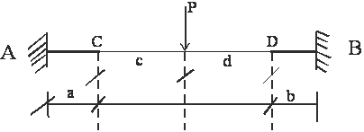 Figure 1: Flexible and stiffened segments of member.
5. Results and Discussion
5.1. Results
Table 1 contains values of bending moment, Mp, of the conjugate system due to external load.
Table 2 depicts bending moment values due to dynamic effect for forcing frequency or function, Rad/sec, for the frame of normal rigid joints and for the frames of stiffened joints. Table 3 presents reactions at imaginary supports due to externally applied loads for the conjugate system. Table 4 contains values of the maximum span moment due to dynamic effect for forcing frequency, Rad/sec for the frame of normal rigid joints and frames of stiffened joints. Table 5 contains values of amplitude of joint displacement due to forced vibration.
Figure 8 is the graph of joint moment, joint 10, due to forced vibration versus stiffening factor,α and β. Figure 9 shows the graph of the maximum span moments due to forced vibration, versus stiffening factors, α and β. Figure 10 presents the graph of joint moment, joint 11, due to forced vibration, versus stiffening factor, α and β. Figure 11 depicts the graph of joint moment, joint 12, due to forced vibration, versus stiffening factor, α and β. Figure 12 shows the graph of amplitude of joint displacement due to forced vibration versus stiffening factor, α and β.
5.2. Discussion
- With joint stiffening of double-bay frames, the bending moments due to dynamic effect are greater over the supports than they are at the mid-spans and hence the beam does not materially affect the stresses. This is more pronounced with increase in length of stiffening, tables 2 and 4.
This very trend is in consonance with fundamental characteristics of the continuous beam structure.
- Values of bending moment over the supports due to dynamic effect, especially with respect to the horizontal members, are smaller for the frame with normal rigid joints than they are for the frames with stiffened joints, table 2, figures 8, 10 and 11. In figure 10, M11-8 tends to exhibit a response that suggests closeness to effect of ‘beating’ on the central column joint of the first upper floor level.
- Values of bending moment at the spans due to dynamic effect are smaller for the frames with stiffened joints than they are for the frame with normal rigid joints table 4, and figure 9.
- The maximum span moments due to dynamic effect decreased progressively with increase in stiffening lengths in such a manner that between stiffening lengths of 425mm and 775mm, this trend passed through zero and migrated to negative values for the frame of stiffened length of 775mm, table 4, and figure 9. This trend suggests an optimal length of stiffening, say lo, exists at which the span moment would hit zero value. This means there must be a stiffening length versus the flexible length at which zero span moments would occur.
- This optimal stiffening length could enable optimal extension of column-free spaces in situations needing as large a column-free space as possible.
- From table 5, it would be observed that joint displacement decreased with increase in joint stiffening. This establishes that joint stiffening increases stability for double-bay building frames.
- Support moments increase with increase in stiffening factor, figures 8, 10 and 11.
- Span moments decrease with stiffening factor, figure 9.
6. Conclusion
On account of diminishing maximum span moment with joint stiffening, stiffening of joints of double-bay frame structure can be utilized to achieve large column-free spaces in building structures and structures of other relevant constructed facilities where, in the first place, large column-free spaces were functionally needed.
One of the benefits derivable from joint stiffening of double-bay frames is not reduction in end, i.e.; support moments, but in the reduction of the maximum span moments even to the barest minimum values.
Since joints stiffening of double-bay multi-storey building frames can bring about shifting or transforming of span moments from positive values, through zero, to negative values, table 4 and figure 9, then, joints of infinite rigidity: (i) substantially reduce deflection; (ii) increase deflection ductility and energy ductility of flexural members as from the instance of substantial reduction in positive span moments; (iii) yields far insignificant a deflection scenario at zero span moments; and (iv) further pushes back the frontiers of deflection concerns for the beams when the span moments are at negative values.
Joint stiffening significantly reduces dynamic joint displacements, table 5, and figure 12, hence, enhances buckling resistance of vertical members. This leads to greater structural stability.
7. Recommendation
Where beams of double-bay multi-storey frames are of reinforced concrete, the span reinforcement due to dynamic effect should be conceived in terms of double reinforcement.
This is because span moments, depending on the stiffening lengths versus flexible lengths provided, can shift from positive value stance to the negative value stance, when operating within dynamic regime scenario.
8. Area for Further Investigation
This lies in establishment of functional relationship between stiffening lengths, flexible lengths and the overall lengths of beam spans for double-bay frames of stiffened joints so as to achieve as large a column-free space as necessary for design and construction of double-bay framed structures.
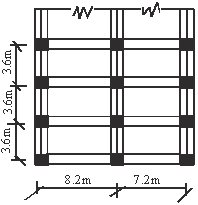 Figure 2: Plan of double-bay multi-storey building framed structure
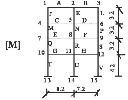 Figure 3: Double-bay four-storey normal rigid building frame
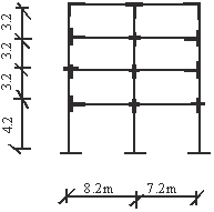 Figure 4: Double-bay four-storey building frame with stiffened joints.
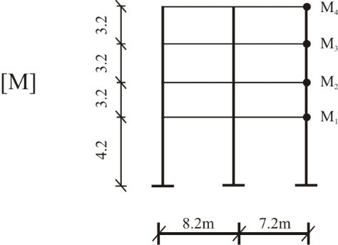 Figure 5: Dynamic model for the double-bay four-storey building frame
q1 = q2 = q3 = 45 KN/m
q4 = 32 KN/m
P1 = P2 = P3 = 15 KN
| 6
|
| 0
|
| (
|
| s
|
| i
|
| n
|
| t
|
| )
|
| KN
|
| q
|
| 4
|
| 0
|
| (
|
| s
|
| i
|
| n
|
| t
|
| )
|
| KN
|
| q
|
| 3
|
| 0
|
| (
|
| s
|
| i
|
| n
|
| t
|
| )
|
| KN
|
| q
|
| 2
|
| 0
|
| (
|
| s
|
| i
|
| n
|
| t
|
| )
|
| KN
|
| q
|
| P
|
| 3
|
| P
|
| 2
|
| P
|
| 1
|
| P
|
| 3
|
| P
|
| 2
|
| P
|
| 1
|
| q
|
| 3
|
| q
|
| 4
|
| q
|
| 2
|
| q
|
| 1
|
| 4.1
|
| 4.1
|
| 3.6
|
| 3.6
|
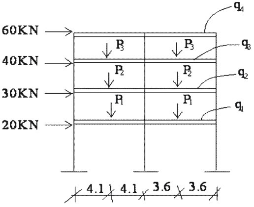 Figure 6: Loading for the conjugate system of the frames
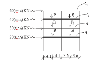 Figure 7: Dynamic loading for the frames
Table 1: Bending moment, Mp, of the conjugate system due to external load for the frames
| Normal Rigid Frame: a=b=0
(KNM) |
Stiffened Frame a=b=275mm
(KNM) |
Stiffened Frame
a=b=425mm (KNM) |
Stiffened Frame
a=b=775mm (KNM) |
|
| M1-2 | -136.62502 | -172.47558 | -198.63228 | -263.02094 |
| M1-4 | -136.62502 | -172.47558 | -198.63228 | -263.02094 |
| M2-1 | -203.58353 | -246.81158 | -277.60053 | -340.09485 |
| M2-5 | -27.00186 | -31.22164 | -33.75587 | -35.66880 |
| M2-3 | -176.58166 | -215.58994 | -242.84467 | -304.43605 |
| M3-2 | -94.13145 | -123.02986 | -144.95843 | -205.87282 |
| M3-6 | -94.13145 | -123.02986 | -144.95843 | -205.87282 |
| M4-1 | 106.89054 | 138.2269 | 161.87205 | 226.32273 |
| M4-5 | -186.96919 | -231.93461 | -263.83615 | -343.20268 |
| M4-7 | -80.07865 | -93.71190 | -101.96411 | -116.87991 |
| M5-4 | -217.48193 | -260.85209 | -290.78084 | -362.02720 |
| M5-2 | 21.56789 | 25.48206 | 27.99247 | 32.29713 |
| M5-6 | -179.20534 | -217.25063 | -244.03847 | -308.60470 |
| M5-8 | -16.70870 | -18.11940 | -18.74990 | -21.12537 |
| M6-3 | 76.41084 | 101.80996 | 121.56509 | 178.96965 |
| M6-5 | -136.44870 | -175.19812 | -203.70035 | -276.92450 |
| M6-9 | -60.03786 | -73.38815 | -82.13529 | -97.95490 |
| M7-4 | 82.99792 | 97.43619 | 106.23188 | 120.81081 |
| M7-8 | -187.0732 | -231.68649 | -263.43549 | -343.58384 |
| M7-10 | -104.00609 | -134.22557 | -157.20359 | -222.77299 |
| M8-7 | -221.03678 | -265.47049 | -296.16996 | -369.23204 |
| M8-5 | 17.28348 | 18.81324 | 19.50037 | 21.15220 |
| M8-9 | -182.67231 | -221.78523 | -249.32369 | -314.71870 |
| M8-11 | -21.08097 | -24.87200 | 27.34590 | -33.36115 |
| M9-6 | 61.38549 | 75.13015 | 84.14297 | 100.60216 |
| M9-8 | -136.62009 | -175.16930 | -203.54165 | -277.13180 |
| M9-12 | -75.23460 | -100.03917 | -119.39868 | -176.52966 |
| M10-7 | 122.09500 | 155.67195 | 180.58150 | 249.46969 |
| M10-11 | -196.85976 | -242.95370 | -276.05115 | -361.38748 |
| M10-13 | -74.764.75 | -87.28173 | -95.46964 | -112.01783 |
| M13-10 | 37.38238 | 50.16981 | 59.11203 | 80.56297 |
| M11-10 | -253.18853 | -305.39068 | -341.49867 | -427.18030 |
| M11-8 | 24.30368 | 28.33032 | 30.85063 | 36.98969 |
| M11-12 | -214.20411 | -261.47907 | -294.72287 | -373.92497 |
| M11-14 | -14.68074 | -15.58128 | -15.92514 | -16.26565 |
| M14-11 | 7.34037 | 5.68577 | 9.86039 | 11.69822 |
| M12-11 | 141.19614 | -179.66665 | -208.24449 | -283.95688 |
| M12-15 | -53.46003 | -64.29897 | -71.73173 | -87.34170 |
| M15-12 | 26.73002 | 36.95925 | 44.41421 | 62.81595 |
| M12-9 | 87.73608 | 115.36768 | 136.51274 | 196.61519 |
Table 2: Bending moment due to dynamic effect for Rad/Sec
| Normal rigid Frame: a=b=0
(KNM) |
Stiffened Frame a=b=275mm
(KNM) |
Stiffened Frame
a=b=425mm (KNM) |
Stiffened Frame
a=b=775mm (KNM) |
|
| M1-2 | -116.03486 | -161.60428 | -179.20319 | -268.24866 |
| M1-4 | -116.03486 | -161.60428 | -179.20319 | -268.24866 |
| M2-1 | -221.12689 | -256.37968 | -294.13419 | -334.95391 |
| M2-5 | -64.16006 | -51.78553 | -71.86412 | -24.07263 |
| M2-3 | -156.96699 | -204.59211 | -222.27504 | -310.87573 |
| M3-2 | -116.79310 | -135.31369 | -167.99186 | -199.34768 |
| M3-6 | -116.79310 | -135.31369 | -167.99186 | -199.34768 |
| M4-1 | 89.74401 | 127.93788 | 147.96153 | -225.19658 |
| M4-5 | -160.36169 | -219.65840 | -234.90723 | -358.59200 |
| M4-7 | -70.61768 | -91.72758 | -86.94576 | -133.39538 |
| M5-4 | -241.58140 | -272.22151 | -318.13336 | -347.25584 |
| M5-2 | 53.58140 | 44.61527 | 59.88292 | 68.63167 |
| M5-6 | -151.61094 | -204.06030 | -211.64822 | -327.02729 |
| M5-8 | 36.70641 | -23.54337 | -46.60223 | 88.86021 |
| M6-3 | -166.23023 | -189.27895 | -237.62631 | -257.90698 |
| M6-5 | 95.41714 | 113.39282 | 138.38718 | 178.56129 |
| M6-9 | -70.81309 | -75.88332 | -99.23915 | -79.35011 |
| M7-4 | 57.66173 | 79.53900 | 72.83115 | 126.43404 |
| M7-8 | -182.90571 | 0243.13451 | -263.50706 | -378.42561 |
| M7-10 | -125.24067 | -163.57431 | -190.67589 | -252.05199 |
| M8-7 | -224.25507 | -254.45280 | -295.44738 | -334.67612 |
| M8-5 | 50.54224 | 37.28057 | 63.64087 | 6.18210 |
| M8-9 | -179.11818 | -234.65492 | -250.33966 | -358.20544 |
| M8-11 | 5.40211 | 17.47681 | 18.53928 | 29.70515 |
| M9-6 | -141.05426 | -161.88435 | -203.16814 | -233.33765 |
| M9-8 | 87.71443 | 93.09982 | 119.25638 | 92.96672 |
| M9-12 | -53.33984 | -68.77864 | -83.91176 | -140.37095 |
| M10-7 | 113.80187 | 168.01851 | 184.61312 | 262.13025 |
| M10-11 | -231.775506 | -277.85320 | -318.29110 | -419.70351 |
| M10-13 | -117.97455 | -109.84412 | -133.67800 | -157-56892 |
| M13-10 | 187.93779 | 77.63577 | 120.24978 | 152.47587 |
| M11-10 | -222.66726 | -273.92372 | -303.25845 | -372.29985 |
| M11-8 | 16.79523 | 3.45329 | 3.93718 | 17.57228 |
| M11-12 | -248.46057 | -297.81322 | -339.60256 | -421.87414 |
| M11-14 | 42.58854 | 20.43674 | 40.28170 | 52.00670 |
| M14-11 | -63.86561 | -42.22376 | -61.54693 | -76.50861 |
| M12-11 | -102.54783 | -139.95023 | -159.45947 | -263,14950 |
| M12-9 | 94.05616 | 100.17412 | 128.80553 | 225.84367 |
| M12-15 | -8.49164 | -39.77611 | -30.65392 | -37.30584 |
| M15-12 | -38.32551 | -5.79360 | -53.02507 | -12.128187 |
Table 3: Reactions Rip, at imaginary supports due to externally applied loads for the conjugate system.
| Normal Rigid Frame: a=b=0
(KN) |
Stiffened Frame a=b=275mm
(KN) |
Stiffened Frame
a=b=425mm (KN) |
Stiffened Frame
a=b=775mm (KN) |
||
| R1P | -6.10088 | -7.28869 | -8.05812 | -9.13382 | |
| R2P | 4.18562 | 5.86440 | 7.14125 | 9.91980 | |
| R3P | -2.52118 | -3.89780 | -5.00249 | -7.94773 | |
| R4P | 2.44925 | 2.33683 | 3.38925 | 4.26989 |
Table 4: Maximum Span Moment Due to Dynamic Effect for Rad/Sec
| Normal Rigid Frame: a=b=0
(KNM) |
Stiffened Frame a=b=275mm
(KNM) |
Stiffened Frame
a=b=425mm (KNM) |
Stiffened Frame
a=b=775mm (KNM) |
|
| M1-2 | 113.88439 | 73.01301 | 46.27978 | -20.60809 |
| M2-3 | 77.96550 | 45.82138 | 20.11064 | -37.11031 |
| M4-5 | 119.22989 | 74.09292 | 43.86895 | -32.92392 |
| M5-6 | 88.26692 | 50.51787 | 22.55022 | -44.67972 |
| M7-8 | 130.41961 | 85.20633 | 54.52278 | -22.55085 |
| M8-9 | 98.91377 | 60.84072 | 32.24611 | -35.36522 |
| M10-11 | 138.7784 | 90.11540 | 55.22522 | -30.00167 |
| M10-12 | 110.11582 | 67.31541 | 37.92739 | -65.14092 |
Table 5: Amplitude of Joint Displacement Due to Forced Vibration
| Stiffening factor |
X1 |
Joint
X1 |
Displacement (mm)
X3 X4 |
|
| a= b = 0
α= β = 0 |
4.94 |
5.86 |
6.07 |
8.36 |
| a= b = 275
α= β = 0.044 |
3.30 |
4.63 |
5.03 |
6.52 |
| a= b = 425
α= β = 0.064 |
2.77 |
3.54 |
4.28 |
5.24 |
| a= b = 775
α= β = 0.134 |
1.85 |
2.02 |
3.04 |
4.12 |
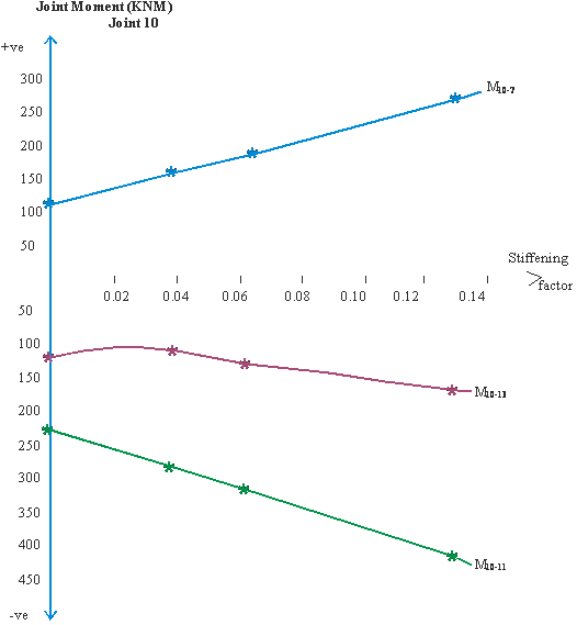 Figure 8: Graph of joint moment due to forced vibration, dynamic effect, versus stiffening factor, α and β.
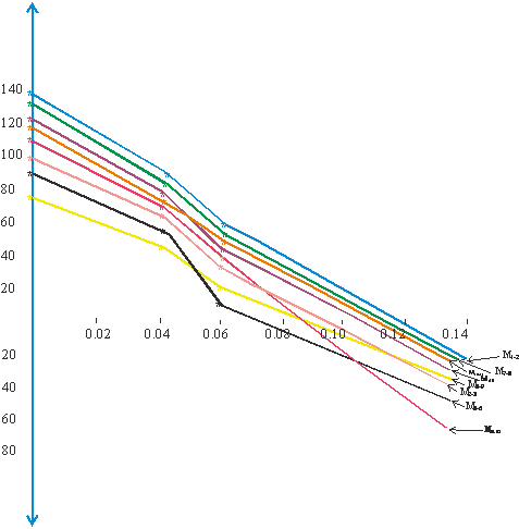 Figure 9: Graph of maximum span moments due to dynamic effect, versus stiffening factor, α and β.
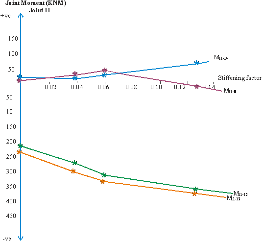 Figure 10: Graph of joint moment, joint 11, due to forced vibration, dynamic effect, versus stiffening factor, α and β.
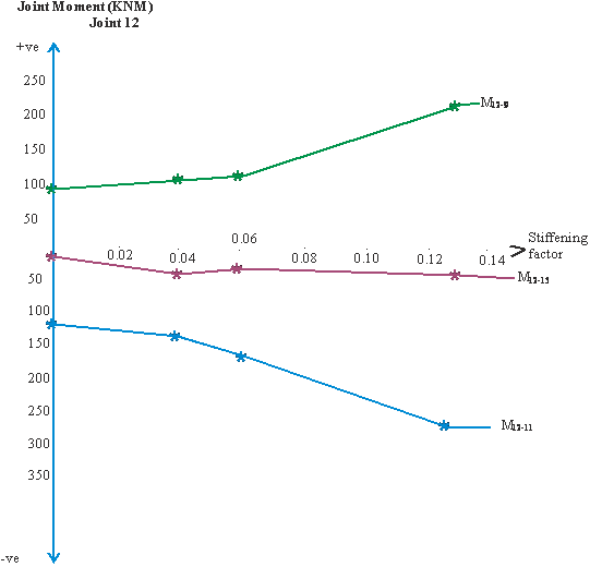 Figure 11: Graph of joint moment, joint 12, due to forced vibration, dynamic effect, versus stiffening factor, α and β.
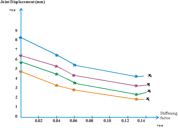 Figure 12: Graph of amplitude of joint displacement due to forced vibration, dynamic effect, versus stiffening factor, α and β.
- Bhatt, P., Programming the Matrix Analysis of Skeletal Structures, Ellis Horwood Limited, England, 1986.
- Bachmann, H., Ammann, W. J.,Dejschl, F., Elsenwan, J.,Floegl, I., Hirsch, G. H., Kiew, G. K., Iande, G. J., Maurenhltz, O., Natky, H. G., et al, Vibration Problems in Structures, BirkhauserVerlag, Basel, 1995.
- Chopra, A. K., Dynamics of Structures Theory and Application to Earthquake Engineering, Pearson, New Delhi, 2012.
- Mbanusi, E. C. and Obodoh, D. A., Free Vibration Response of Double-Bay Multi-Storey Building Frames with Stiffened Joints, Int’l J. of Engineering and Computer Science, Vol. 5, Issue 5, May 2016, pp. 16620 – 16638.
- Sundararajan, C. R., Structural Vibration Analysis, Design and Troubleshooting. http://www.training.bossintl/com/htmstructural-vibration-analysis.htm/11/1/2006.
- Thomson, W. T., Theory of Vibration with Application, third ed. CBS Publishers and Distributors, Delhi, 2007.
- Polyakor, S. V., Design of Earthquake Resistant Structures, Mir Publishers, Moscow, 1985.
- Hemant, B. K., Durgesh, C. R. and Sudhr, K. J., A case for use of Dynami Analysis in Designing for Earthquake Forces, Scientific Corresponding. www.iitk.ac.in/nicee/RP/2006,dynamic-analysis-current-sciencepdf,2006.
- Osadebe, N. N., Stress Analysis of Frames with Stiffened Joints, Proceedings on the 4th International Conference on Structural Engineering Analysis and Modeling, SEAM, Accra, 1997, pp. 136 – 145.
- Masur, E. F., “Discussion on Effect of Joint Rotation on Dynamics of Structures” ASCE, Mechanics Division, Vol. 88, 1962, pp. 83 – 85.
- David, J., Advanced Structural Mechanics, Thomas Telford, London, 2000.
- Anya, C. U., “Dynamic Analysis of Tall Buildings”, M. Eng. Thesis, Department of Civil Engineering, University of Nigeria, Nsukka, Nigeria, 1995.
- Aminu, B. N. “Matrix Analysis of Multi-Storey Building Frame with Stiffened Joints”, M. Eng. Dissertation, Department of Civil Engineering, Enugu State University of Science and Technology, Enugu, Nigeria, 1995.
- Ezeokpube, G. C. and Osadebe, N. N., “Effects of Joint Stiffening on the Dynamic Response of Frames”, Nigerian J. of Technology, NIJOTECH, Vol. 29 No. 1, March, 2010, pp. 1-8.
No related articles were found.