Indoor Positioning and Path Planning Platform for iRobot Create 2 Sweeping Robot

Adv. Sci. Technol. Eng. Syst. J. 4(3), 198–206 (2019);
 DOI: 10.25046/aj040327
Many robots have been proposed for smart applications in recent years However, while these robots have good ability to move between fixed points separated by short distances, they perform less well when required to navigate complex interior spaces with an irregular layout and multiple obstacles due to their relatively crude positioning and path control capabilities. Accordingly, the present study proposes an integrated system consisting of a Raspberry Pi development platform, various sensor devices and iBeacon technology to facilitate the path control, indoor positioning, and obstacle avoidance of a programmable iRobot Create 2 sweeping robot. The capabilities of the proposed system and its various components are investigated by means of practical experiments and numerical simulations. In general, the results confirm that the proposed integrated system provides a viable platform for the future development of sophisticated indoor robots for smart indoor applications.
1. Introduction
In recent years, robot technology has been introduced into related application of smart network. However, interior space is a very complicated environment because signal transmission can be easily influenced by architectural structure. Thus, for many years, well-known services to the mess such as GPS positioning system or Google map are most applied in outdoor public infrastructure instead of interior space. This has blocked the application of robots in smart homes; at present, smart robots mostly move between fixed points, on certain tracks or only in short distance; for the movement in interior space of robots, there have not proper solutions because researches in this field is still in startup stage and robots are in lack of the support in IoT environment; plus, problems emerged when it comes to the sensing technology, spatial orientation, path planning, obstacles avoidance, robot learning and communication between robots still need to be solved and overcome by further integration.
To introduce the application of robots from factories to homes, we need to enable smart robots to arrive the right position rapidly through the indoor application service or precisely identify robots or users via indoor positioning navigation. Thus, it is necessary to conduct further research on smart robots to develop a positioning service system used indoor. In this way, smart robots can be extended from industrial application in factories to caring service in smart homes, bringing more diverse possibilities to home application service of IoT.
This study is organized as below: Section 2 introduces related work on indoor positioning, path planning and searching, avoiding obstacles and automatic following; Section 3 introduces research steps and system implementation; Section 4 represents conclusions.
2. Research on related application of home robots
How to let robots assist people to deal with daily tasks in various scenarios and precisely identify their location and arrive target areas to complete tasks will be important goals to introduce robots to smart home application. The following are some related study of home robots.
2.1. Indoor positioning
In view of this, [1] proposed to utilize RSSI signal of wireless network and triangulation algorithm as be indoor positioning mechanism for robots. The results showed the positioning precision is 0.125 m and the error is below 0.4%.
In [2], the author proposed to utilize laser distance meter to construct indoor environment model. The meter can measure its moving path and calculate via the assistance of cloud server, effectively avoiding obstacles on moving path. In [3], it proposed to utilized the information change in the sensor or the robot and calculate its moving direction and location. Through change values measured by gyro and accelerometer, the robot can calculate its X, Y and θ. After calibration, it can obtain the reference coordinate of robots and plan an effective moving path.
2.2. Path planning
Coverage path planning [4] algorithm for robots is an important efficiency indicator for home robots; random path planning is an intuitive way to move of robots. Robots forward linearly towards any direction and change path only when hitting on obstacles and repeat this process until it reaches maximum coverage scope. Such algorithms have the advantage of simplicity since very few sensors are required and there is no need to construct and maintain an indoor environment map [5]. However, they require a long time to achieve full coverage of the target environment; DmaxCoverage [6] an algorithm which can assist robots to construct environment map to reach maximum coverage scope; furthermore, in [7], this study utilized Dijkstra’s algorithm to generate optimum path in environment to avoid the decrease of efficiency during random path planning.
2.3. Search, obstacle avoidance and automatic follow-up
Unlike robots, humans can use their own sense organs to create space and sense of distance. Therefore, in [8] this paper implements a mobile robot with an automatic following system. The mobile robot can perform positioning, mapping, and moving the target side. Tasks such as distance, human detection and target tracking, and can be applied in real life, such as museum, office or library guidance; in [9], this paper implements a wheeled robot that can perform search and obstacle avoidance work. The robot is equipped with a vision and distance sensor, which can match multiple objects by visual system identification objects to create multiple hypothesis blocks for the environment. These multiple hypothesis blocks can make the robot avoid obstacles and explore the target object.
3. System design and implementation
Figure 1 shows the functional block diagram of the implemented robot. The function of positioning is a crucial factor to introduce robots into interior application. To achieve this goal, this study combines Raspberry Pi with BLE Bluetooth communication technology to implement iBeacon of robots; when the robot moves, if it detects iBeacon and reports the positioning information, the system is able to know the location of the robot.
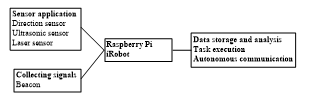 Figure 1: System block diagram of the sweeping robot
Figure 2 shows the original look of programmable sweeping robot. This study combines iRobot Create 2 programmable sweeping robot with Raspberry Pi programmable control electric circuit with I/O device to explore straight movement and rotation of robots. We also use Python to write tests of every control application. developing a smart robot which is equipped with indoor positioning function; Figure 3 is the prototype of the robot for indoor application.
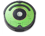 Figure 2: Programmable Sweeping Robot (Original Look)
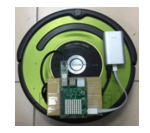 Figure 3: Smart Robot Developed by Combining iRobot Create 2 Programmable Sweeping Robot with Raspberry Pi
3.1. Composite sensing device
Linear walking and rotation are the basic movement instructions of the robot. In order to understand the difference between the expected result and the actual result after the instruction is executed, this study installed sensing devices such as distance, magnetic field, acceleration, and gyroscope on the cleaning robot. This study first measure the robot’s motion data and then use the analysis results to correct the robot’s motion parameters.
Show as Figure 4, take the orientation sensor as an example. After the robot adds the orientation sensor, the system developer can use the sensor’s numerical change to determine the robot’s movement state; because the X axis represents the robot’s direction of travel, the robot can use it to determine the robot when performing a task. The forward direction; on the other hand, since the Z axis of the accelerometer is negative when the robot’s operation panel is upward and downward when it is positive, it is possible to use the Z axis of the acceleration sensor to detect whether the robot is running when the robot is operated. Overturned or tilted state.
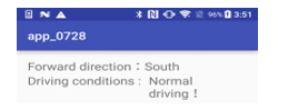 Figure 4: The result of the smart robot orientation and the tilt state of the car body
3.2. Robot moving path planning mechanism
To enhance the accuracy of control command, we need to measure reaction delay time and error when executing assigned process after robots receive commands.
3.2.1. Measure and Observe the Straight Movement
To enhance the accuracy of control command, we need to measure reaction delay time and error when executing assigned process after robots receive commands.
Assume the program execution time is 10.05 seconds to 11.00 seconds, and forwarding speed of the robot is set as 200 mm/sec; Table 1 shows the measured moving distance of the robot at different second.
As shown in Table 1, the experimental results indicate after the control device gives commands to the robot, the actual complete time of robots executing commands will have delay for about 0.5155 second (time error) and the average value of distance error is 10.1662 cm. This result can be used by the system to modify parameters so as to enhance the accuracy of positioning of the robot.
Table 1: Computed Measured Results of Experimented Robot Move Straightly for 11 Seconds
| Execution
Time |
Time Error | Computed
Distance |
Actual Distance | Distance
Error |
| 10.5657 | 0.5157 | 211.3148 | 200.0 | 11.3148 |
| 10.6153 | 0.5153 | 212.3066 | 201.9 | 10.4066 |
| 10.7120 | 0.5120 | 214.2402 | 203.5 | 10.74024 |
| 10.8067 | 0.5067 | 216.1356 | 205.9 | 10.2356 |
| 10.9189 | 0.5189 | 218.3784 | 208.0 | 10.3784 |
| 11.0167 | 0.5167 | 220.3347 | 210.0 | 10.3347 |
| 11.1192 | 0.5192 | 222.3845 | 212.0 | 10.3845 |
| 11.2163 | 0.5163 | 224.3278 | 214.3 | 10.0278 |
| 11.3168 | 0.5168 | 226.3371 | 217.0 | 9.3371 |
| 11.4165 | 0.5165 | 228.3313 | 219.0 | 9.3313 |
| 11.5168 | 0.5168 | 230.3377 | 221.0 | 9.3377 |
| 0.5155 | 10.1662 |
According to the above measurement it is found when speed is fixed, we can obtain stable second difference and stable distance difference. Thus, when controlling the moving distance of robots, we can do corrections by substituting values into the Eq.(1):
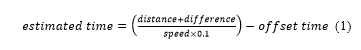 Amongst, distance indicates predetermined moving distance, difference indicates error correction distance, offset time indicates delay time of actual execution; from measured results in Table 2 it is known: let difference = 10.1662, offset time = 0.5155, assume predetermined straight moving distance of the robot is 800 cm and then the values adding into the Eq.(2):
![]() Through this equation we obtain predetermined execution time of the program is 39.9928 seconds; after the program is execute, we obtain the actual execution time of the robot 40.5387 seconds, moving distance is 799 cm; the measured results show after adding it to the correction equation, the actual moving distance of the robot 799 cm is close to the predetermined value 800 cm, and difference is about 0.125%.
Through this equation we obtain predetermined execution time of the program is 39.9928 seconds; after the program is execute, we obtain the actual execution time of the robot 40.5387 seconds, moving distance is 799 cm; the measured results show after adding it to the correction equation, the actual moving distance of the robot 799 cm is close to the predetermined value 800 cm, and difference is about 0.125%.
Table 2: Measured Results after Adding the Straight Walk to the Correction Equation
| Actual Seconds | Second Difference | Actual Distance |
| 40.5387 | 0.5459 | 799 |
3.2.2. Measure and Observe the Rotation Angle
To observe whether the rotation angle and direction of the robot are as what we have predicted, we combine the mobile sensor with the robot. Through function of iPhone DeviceMotion we obtain the measurement data of the robot; experimental data here will be compared with that obtained from SenseHat compound sensor; Table 3 shows the measured results by observing rotation angle per second after the robot finishes straight move and another move for 1.1~3.3 seconds at 100 mm/sec rotation speed. The testing process is shown in Figure 5.
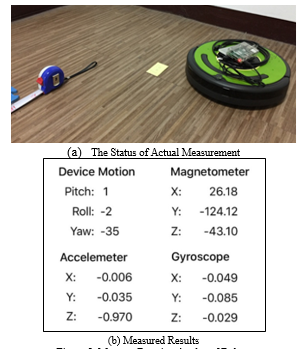 Figure 5: Measure Rotation Angles of Robots
From the experimental results we know when rotation speed is fixed, dividing actual angle by program seconds will obtain rotation angle per second, rotation angle per second is stable and thus we obtain the equation below:
 Let expected denote the predetermined rotation angle, average denote the actual angle/ obtained average rotation angle according to program execution seconds (control factor) According to the measured results in Table 3, let average = 55.21061296∘/sec; during the execution, we simply need to substituting the degree of angle to rotate into the above-mentioned equation to obtain the required seconds for rotating to the assigned angle; taking rotating 90-degree angle as example, through the equation we obtain the execution time of the program will be expressed as execution time = 90 / 55.21061296 = 1.6301 seconds.
Table 3:: Actual Measured Results of Rotation Angles of Robots
| Execution Time in Seconds | Rotation
Angle |
Rotation Angle Per Second |
| 1.502199 | 55 | 55 |
| 1.602238 | 61 | 55.45454545 |
| 1.702244 | 67 | 55.83333333 |
| 1.802489 | 72 | 55.38461538 |
| 1.902531 | 77 | 55 |
| 2.002577 | 83 | 55.33333333 |
| 2.102841 | 88 | 55 |
| 2.202954 | 93 | 54.70588235 |
| 2.302842 | 100 | 55.55555556 |
| 2.403040 | 104 | 54.73684211 |
| 2.503230 | 109 | 54.5 |
| 2.603253 | 117 | 55.71428571 |
| 2.703390 | 122 | 55.45454545 |
| 2.803547 | 126 | 54.7826087 |
| 2.903717 | 132 | 55 |
| 3.003546 | 139 | 55.6 |
| 3.103666 | 142 | 54.61538462 |
| 3.203762 | 149 | 55.18518519 |
| 3.303927 | 153 | 54.64285714 |
| 3.404050 | 161 | 55.51724138 |
| 3.504325 | 165 | 55 |
| 3.604233 | 171 | 55.16129032 |
| 3.704476 | 176 | 55 |
| 55.21061296 |
Table 4 shows the results obtained when the robot rotated 90 degrees, 180 degrees, 270 degrees, and 360 degrees. It can be seen from the experimental results that with the increase of the program execution time, the errors generated by the robot after the execution of the rotation action will gradually appear.
Table 4: Actual results of the angles obtained after actual implementation
| Estimated rotation angle | Calculated time | Actual execution time | Actual rotation angle | Angle error |
| 90 | 1.6301 | 2.132857 | 91 | 1 |
| 2.133154 | 90 | 0 | ||
| 2.132777 | 91 | 1 | ||
| 2.133019 | 87 | 3 | ||
| 2.132970 | 91 | 1 | ||
| 2.132866 | 90 | 0 |
- 90 degrees
| Estimated rotation angle | Calculated time | Actual execution time | Actual rotation angle | Angle error |
| 180 | 3.2602 | 3.762850 | 180 | 0 |
| 3.764159 | 183 | 3 | ||
| 3.762853 | 180 | 0 | ||
| 3.763769 | 181 | 1 | ||
| 3.764353 | 181 | 1 | ||
| 3.764293 | 180 | 0 |
- 180 degrees
| Estimated rotation angle | Calculated time | Actual execution time | Actual rotation angle | Angle error |
| 270 | 4.8904 | 5.396417 | 269 | 1 |
| 5.396603 | 272 | 2 | ||
| 5.396394 | 268 | 2 | ||
| 5.396588 | 268 | 2 | ||
| 5.396419 | 271 | 1 | ||
| 5.396533 | 270 | 0 |
- 270 degrees
| Estimated rotation angle | Calculated time | Actual execution time | Actual rotation angle | Angle error |
| 360 | 6.5205 | 7.028154 | 357 | 3 |
| 7.028164 | 362 | 2 | ||
| 7.028282 | 362 | 2 | ||
| 7.028401 | 362 | 2 | ||
| 7.028339 | 362 | 2 | ||
| 7.028357 | 362 | 2 |
(d) 360 degrees
SenseHAT is an expansion board for the Raspberry Pi. As shown in Figure 6, since the robot’s magnetic field will affect the SenseHAT’s value, in order to improve the accuracy, SenseHAT will calibrate the magnetic field, and then measure the SenseHAT detection value is correct. Table 5 uses the rotation angle of 72 degrees as an example to judge the difference between the predicted angle and the actual angle. The maximum value of the experimental result drops to 5, so it needs to be corrected after each rotation command
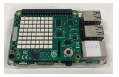 Figure 6: SenseHAT composite sensor
3.2.3. Measure and Observe the Rotation Angle
As mentioned above, the movement of robots is consisted of two parts including straight movement and rotation. Thus, we can write its moving path into script and then through changing commands to make robots execute tasks. Let s denote straight moving, t denote back moving, r denote right turn and l denote left turn. Taking Figure 7 as example, the script of the moving path of the robot will be written into “s290 r90 s47 l90 s310 r30 s122.” if we break down the script by rules, it can be divided into seven command list including forwarding 290 cm, rotating right for 90-degree angle, forwarding 47 cm, rotating left for 90-degree angle, forwarding 310 cm, rotating right for 30-degree angle, forwarding 122 cm and arriving the destination.
Table 5: Experiment with a rotation of 72 degrees
| Initial angle | Estimated rotation angle | Actual rotation angle | Angle error |
| 105 | 177 | 180 | 3 |
| 249 | 251 | 2 | |
| 321 | 323 | 2 | |
| 33 | 38 | 5 | |
| 105 | 106 | 1 | |
| 178 | 181 | 3 | |
| 250 | 253 | 2 | |
| 322 | 323 | 1 | |
| 34 | 38 | 4 | |
| 106 | 106 | 0 |
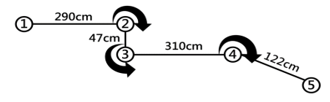 Figure 7: Moving Path Planning of Robots
3.2.4. Production of script tools
Although the path of the robot can use the previously written script to write the relevant parameters to the robot. However, in order to make the robot’s control more flexible, the project also developed a Web control interface that allows the user to control the walking path of the robot through the Web, as shown in Figure 8:
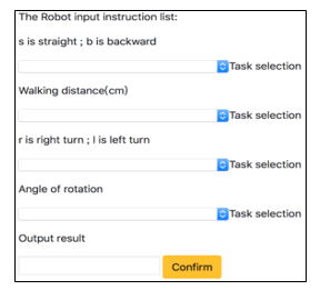 Figure 8: Manual specification of robot path
When the user issues an instruction, the system will put each value into the database and then convert it to json format output when needed, as shown in Figure 9
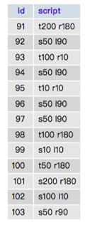 Figure 9: Store forward distance and turning angle
As shown in Figure 10, when robots execute Script, it would obtain forwarding distance and rotation angles from the database to execute tasks. When all assigned tasks are done, it would show the spent time for finishing all movements to notify users of time spent to complete cleaning so that users can more easily use it.
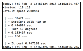 Figure 10: Executed Motions and Spent Time of Robots
3.3. The Design of iBeacon Information Assist System
Owing to smart robots can provide more human-oriented location-based service after combining with perception positioning system and have better market competitiveness in the future, this study new robot communication application service in view of the development of smart home and IoT. This study implements diverse simulation test by iRobot Create2 which is designed to control robots, applying iBeacon micro-location technology, compound multi-axis sensor technology and so on to develop smart robots for indoor positioning and path algorithm; for robots, the precision of positioning signals is a very crucial parameter.
3.3.1. Experimental field planning and design
To enable robots to obtain indoor coordinates and execute dynamic searching, this study constructs an IoT micro-location system. Through the assistance of the iBeacon system, robots are able to inquire past moving track before executing tasks and transform the moving process to coordinate record to build up the spatial perception ability of robots; when robots calibrate signals and connect to system database. The robot can report its location to the system while forwarding and meanwhile report its location to the IoT micro-location system so that it can plan, correct and predict its paths.
Fig. 11 shows the experimental field. The experimental field is an 85m x 20m 2-dimensional space. A total of 14 Beacons are arranged to allow the robot to perform tasks that can be used for positioning applications.
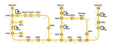 Figure 11: Experimental space for robotic indoor positioning applications
3.3.2. Researches on Beacon Positioning
The iBeacon messages detected by the robot contained various items of location-related information, including the UUID, the Tx Power, the RSSI, and so on (see Fig. 12)
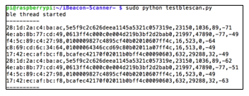 Figure 12: Contents of iBeacon message
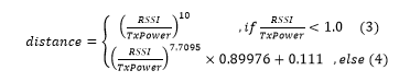
After obtaining RSSI and TxPower value between robots and Beacon, we can then use relative relation between RSSI and TxPower as the reference value of distance between the robot and Beacon; when ratio between RSSI and TxPower is less than 1.0, we use Eq. (3) to obtain distance, or we will use Eq. (4):
Scan the iBeacon through the Raspberry Pi and calculate the distance, as shown in Figure 13, but since this method is easy to generate large fluctuations through real-time operation, it is necessary to increase the stability of the distance by accumulating balance, and plan two points iBeacon to be placed at 0.5m and 2.5m, 30 points are measured for each point, and the first 10 data are averaged, and then the last 20 data are corrected by the EWMA formula to obtain the distance. Figure 14 is the experimental results.
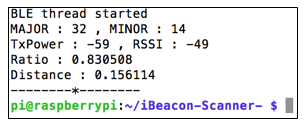 Figure 13: Raspberry Pi Scan iBeacon and Calculate Distance
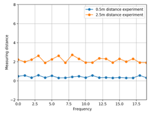 Figure 14: Revise the distance of iBeacon
3.4. Robot positioning and map construction
Safe walking is a challenge when robots enter an unknown environment. SLAM technology can be used to map assisted positioning by reading the value of the surrounding environment by the sensor.
3.4.1. Robot Operating System
With the warming of domestic robots in the past two years, autonomous positioning has become the primary threshold for robotic intelligence. To realize this function, many manufacturers have chosen to use ROS as the operating system of robots.
ROS is more like an application role as a communication intermediary software in the entire robot design architecture. At the same time, a complete system integration framework for robot application design based on an existing operating system can be developed in various programming languages such as C++ and Python. Through the functions provided by ROS, the use of SLAM can be made more convenient. Figure 15 shows the use of ROS to generate a simple picture through the virtual machine. It is necessary to constantly correct the map through the SLAM algorithm to make the map more accurate.
3.4.2. SLAM map construction
As shown in Fig. 16, SLAM comprises three components, namely localization, mapping and navigation. With advances in computer technology and sensing capabilities, SLAM has evolved into the method of choice for robots to detect unfamiliar environments and find their way through them. As shown in Fig. 17, various SLAM technologies are available, including VSLAM, Wifi-SLAM and Rplidar SLAM. Among these technologies, Rplidar SLAM is one of the most commonly used and is hence also adopted in the present study.
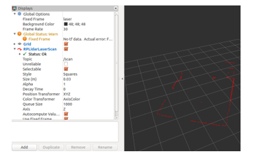 Figure 15: A Depicting map outlines through ROS
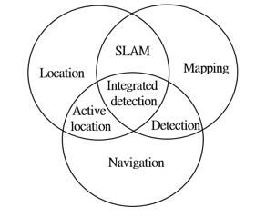 Figure 16: SLAM application diagram
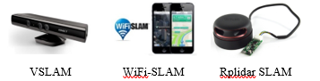 Figure 17: Common SLAM technology
Rplidar Collect data repeatedly, filter noise and produce visual map, Rplidar A2 Typical rotational frequency is 10Hz (600RPM), can realize 0.9° angle resolution at typical rotational frequency, can adjust the rotation frequency in the range of 5Hz-15Hz with the user’s demand.
3.4.3. RPLIDAR Scan Value
As shown in Figure 18, RPLIDAR is performed by Python to perform scanning, and the values of four angles are obtained, which are 0 degrees, 90 degrees, 180 degrees, and 270 degrees, and the results are shown in Table 6, can be applied to robot detection and The distance between obstacles.
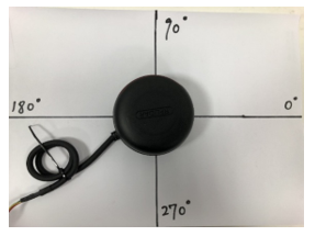 Figure 18: Use Rplidar to get the value of the angle
Table 6: 4 angle values
| Angle | Distance (cm) |
| 0 | 17.6 |
| 90 | 103.3 |
| 180 | 13.4 |
| 270 | 20.0 |
3.4.4. SLAM Algorithm
In the SLAM algorithm, the Hector SLAM algorithm is used. The algorithm developed by Hector Labs in Germany was ported from the original RoboFram algorithm to the ROS package at the end of 2010. Using the 2D mesh method, the value of the laser scan is converted in the xy coordinates by the tf library, and possible position estimation and rendering obstacles. Repeated scanning uses a bilinear filtering method to continuously correct the map with low power consumption, immediacy and goodness. Figure 19 shows the working principle of the Hector SLM, and Figure 20 shows the experimental results of the Hector SLAM scanning virtual machine.
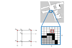 Figure 19: Hector SLAM works
3.5. Robot Obstacle Avoidance
To carry out research on robot obstacle avoidance, the robot is equipped with three ultrasonic sensors. As shown in Figure 21, the ultrasonic sensor can sense a distance of 2cm to 400cm, an accuracy of 0.3cm, and an angle range of 15 degrees. The robot can read the value of the sensor to determine whether it encounters an obstacle, such as Figure 22 shows.
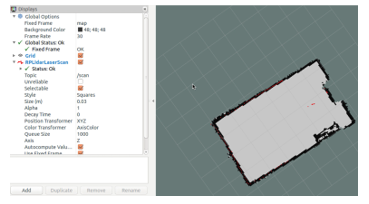 Figure 20: Logo
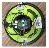 Figure 21: Install an ultrasonic sensor on the robot
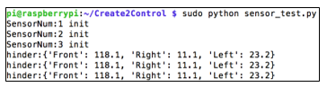 Figure 22: Confirm that the ultrasonic sensor is working
The robot’s ultrasonic sensor determines if an obstacle is encountered in front, and the robot will determine which side is longer by the left and right sensors to determine how to avoid the obstacle. As shown in Fig. 23, when the distance is less than 20 cm, the obstacle avoidance behavior is performed. When the sensor’s value returns to normal, the robot will travel midway through the body to ensure that the robot completely bypasses the obstacle and rotates back to the original path.
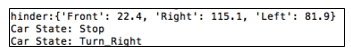 Figure 23: Turning with obstacles less than 20cm
To understand the execution situation of the obstacle avoidance action of the robot, Figure 24 and Figure 25 simulate and observe the execution process of the obstacle encountered by the robot, where the x-axis is time and the y-axis is the path of the robot to avoid obstacles. When the robot turns right the y axis is decremented by 1 , the y axis is incremented by 1 when it is turned left. Figure 24 simulates the robot encountering an obstacle at 2 seconds, then turning right around the obstacle and leaving the obstacle at 4 seconds. Figure 25 simulates the robot encountering an obstacle at 3 seconds, then turns left around the obstacle and leaves the obstacle at 5 seconds.
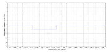 Figure 24: Simulate turn right bypass the obstacle
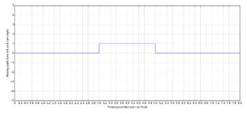 Figure 25: Simulate turn left bypass the obstacle
Let the robot perform the task of bypassing obstacles. From the experimental results, the robot encountered an obstacle within 2.4 seconds, began to perform the action of avoiding the obstacle, and left the obstacle within 3.8 seconds. Figure 26 is the result of the actual walking of the robot. The obtained time is brought into the program, and the result chart of the simulation is shown in Fig. 27, and the actual obstacle avoidance result chart is consistent.
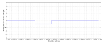 Figure 26: The actual obstacle avoidance result of the robot
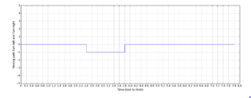 Figure 27: Simulate the results of actual obstacle avoidance
4. Conclusion
This study has developed an integrated development platform for indoor mobile robots consisting of a programmable iRobot Create 2 sweeping robot; a Raspberry Pi computer; a sensing system consisting of laser, magneto, accelerometer, gyroscope and ultrasonic devices; and iBeacon technology. The path planning and positioning performance of the proposed platform has been evaluated experimentally and calibration equations have been proposed for both the linear and rotational motions of the robot. The use of SLAM technology to construct a map of the surrounding environment has been explained. Finally, the ability of the sweeping robot to perform automatic obstacle avoidance maneuvers has been demonstrated numerically and experimentally. In general, the results confirm the basic feasibility of the proposed framework and provide a useful basis for the future development of mobile robots for indoor smart network applications.
- Wengpeng Wang, Xin Wang “Research on robot indoor localization method based on wireless sensor network”, 2015 International Conference on Advances in Mechanical Engineering and Industrial Informatics (AMEII 2015), May 2015.
- Masum Billah, Md. Raisuddin Khan “Smart Inertial Sensor-based Navigation System for Flexible Snake Robot”, IEEE International Conference on Smart Instrumentation, Measurement and Applications (ICSIMA), pp.1-5, Nov. 2014.
- Nieves Pavón-Pulido, Juan Antonio López-Riquelme, Juan Jesús Pinuaga-Cascales, Joaquin Ferruz-Melero, Raul Morais dos Santos “Cybi: A Smart Companion Robot for Elderly People: Improving Teleoperation and Telepresence Skills by Combining Cloud Computing Technologies and Fuzzy Logic “, EEE International Conference on Autonomous Robot Systems and Competitions (ICARSC), pp.198-203, April 2015.
- Abhishek Pandey, Anirudh Kaushik, Amit Kumar Jha,Girish Kapse,”A Technological Survey on Autonomous Home Cleaning Robots”, International Journal of Scientific and Research Publications, Vol. 4, No. 4, April 2014
- Ercan U. Acar, Howie Choset, Yangang Zhang and Mark Schervish, “Path Planning for Robotic Demining: Robust Sensor-Based Coverage of Unstructured Environments and Probabilistic Methods”, The International Journal of Robotics Research, July 2003.
- Feng-Min Chang and Feng-Li Lian, “Inverse observation model and multiple hypothesis tracking for indoor mobile robots”, 2014 IEEE International Conference on Automation Science and Engineering (CASE), pp. 1200-1205, 18-22 Aug. 2014.
- Zeyn Saigol, Bram Ridder, Minlue Wang, Richard Dearden, Maria Fox, Nick Hawes, David M Lane, and Derek Long, “Efficient Search for Known Objects in Unknown Environments Using Autonomous Indoor Robots”, In Workshop on Task Planning for Intelligent Robots in Service and Manufacturing, IROS 2015. October 2015.