Design and Analysis of a Virtual Synchronous Generator Control Scheme to Augment FRT Capability of PMSG-Based Wind Turbine
 , Md. Rifat Hazari 1, 2, Mohammad Abdul Mannan 1, 2, Md. Abdur Rahman 1, 2
Adv. Sci. Technol. Eng. Syst. J. 7(6), 236–243 (2022);
 DOI: 10.25046/aj070626
Massive integration of inverter dominated renewable energy systems (RESs), i.e., wind turbines (WTs), reduces the reliance on conventional alternator-based power stations. The system inertia and damping aspects of the power system were significantly decreased by this extensive integration of inverter-based WT system, which impacts on the fault ride-through (FRT) competence and thus precipitates the frequency instability. Modern grid code instructed to operate the WT system similar like conventional power plants. However, most of the conventional inverter controller failed to fulfil the requirement. To compensate for the issues, an advanced control method of a VSG for variable speed wind turbines with a permanent magnet synchronous generator (VSWT-PMSG) is proposed by this work. The proposed control scheme mimics the behavior of a conventional alternator and includes an active-power frequency control scheme with a governor model accompanied by an automatic voltage regulator (AVR) model, along with a current feedback loop system which enhance the system inertia and consider damping aspects of the system during serious fault conditions, i.e., three line to ground (3LG) fault. The suggested VSG-based inverter controller’s functionality has been verified using the simulation model.
1. Introduction
The importance of moving away from fossil fuels to clean, dependable, and affordable RES is a paramount and immediate concern. Furthermore, being an increasingly important source of intermittent renewable energy, the wind energy generation system begins to have huge effects on the power grids nowadays, considering the increased grid penetration of wind farms (WFs) and updated power level of WTs in the energy generation systems. After all, renewable energies are abundant in nature, clean, and safe compared to other energy sources, an ultimate source of green power, and widely accessible. Undoubtedly, one of the most prominent and efficient sources of renewable energy technologies is wind power.
2022 is predicted to be another significant year for wind power developments, specifically for the quickly expanding offshore wind industry, as stated in the Global Wind Report 2022 from the Global Wind Energy Council (GWEC). Globally, 94 GW of wind capacity have been established, including 21 GW offshore,making 2021 the second-best year for the global wind industry. Offshore installation is about to play a bigger role in the leading global wind capacity development. By 2026, the global offshore wind market is anticipated to expand from 21.1 GW in 2021 to 31.4 GW [1].
Among different types of WT systems, PMSG is a popular alternative for installing new WF because of various advantages, including variable speed operation, ability to regulate active and reactive power autonomously, benefit of omitting the gearbox and brush, and inexpensive maintenance [2-3]. However, a massive integration of PMSG-based WT systems in the power grid reduces dependency on traditional units and influences the power system’s transient stability.
The new grid code required that the WF work in the same way as traditional units and maintain grid stability during transient states. One of the important criteria of voltage stability is fault ride through (FRT) capability [4].
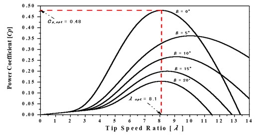
Figure 1: characteristic curve.
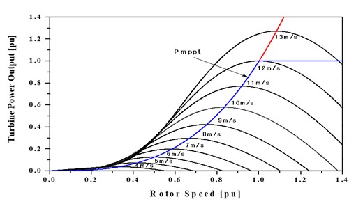
Figure 2: Wind generator power response at different wind speed.
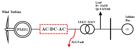
Figure 3: Power system model.
Several control mechanisms have been utilized to augment the FRT capability of the PMSG system. For example, well known cascaded control strategy presented in Refs. [5-7]. However, the conventional cascaded control mechanism can’t ensure FRT capability properly.
Also, some auxiliary devices, for example, supercapacitors [8], energy storage systems (ESS) [9], static synchronous compensators (STATCOM) [10], unified power flow controllers (UPFC) [11], flywheel energy storage system (FESS) [12] and superconducting magnetic energy storage (SMES) [12] etc., has been applied to augment FRT competence of PMSG system. However, all the auxiliary devices will increase the overall system cost.
Additionally, some inherent control modifications can be made for PMSG to improve the FRT capability. For example, The machine-side converter (MSC) regulates the DC-link voltage and the wind turbine’s grid-side converter (GSC) accomplishes the maximum power point tracking (MPPT) in the new control scheme [13].
As a result, the surplus power on the DC-side may be lowered by decreasing the active power generated by the PMSG when the grid-side voltage drops. Thereafter, DC-side voltage stability is simplified. However, in typical conditions, the performance of the control technique mentioned above is erroneous.
In [14], pitch control was used to cut down on the available wind power. The rotor and the DC-link capacitor store the additional power. The GSC also provided the backup for reactive power. The pitch control,on the other hand, is a slow mechanical process that can’t respond right away to changes in the system. Also, changing the angle of the pitch too often wears down equipment and shortens the life of the PMSG.
Recently, Researchers are actively concentrating on inverter systems established on VSG principle [15]. In Reference [16] portrayed a basic concept that aims to mimic the properties of a SG while simultaneously providing dampening and inertial support.
Based on the aforementioned contemplations, developing a control scheme based on the VSG technology that enables the PMSG system to improve FRT competency of the system is the main goal of the work. The AVR, damping characteristics, and mechanical governor behavior are all emulated by the suggested inverter control technique for PMSG. With the help of AVR, the proposed VSG system will inject the right amount of reactive power to restore the voltage level.
To assist with the proposed work, the performance of a PMSG-based WF was evaluated in terms of its FRT capabilities, taking into account the 3LG fault, which is the most severe situation. The simulation exhibits the FRT capabilities of the proposed VSG control technique as well as the smooth operation of the PMSG system.
2. Wind Turbine Model
WT power generation relies upon the interaction of the turbine rotor with the wind.
Accessible wind power,
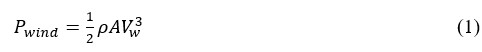
Here, A and Vw are the area used by rotor blades and wind speed, respectively.
In accordance with the Betz law, under an ideal state of affairs, the maximum power that an ideal turbine rotor with an infinite number of blades can produce from wind is 59.26% of the power accessible in the wind.
WTs are restricted to having two or three rotor blades because of underlying and economic contemplations. Thus, how much power they can pull out is nearer to around 50% of the accessible wind power. The Power coefficient represents the ratio of obtainable power to available power.
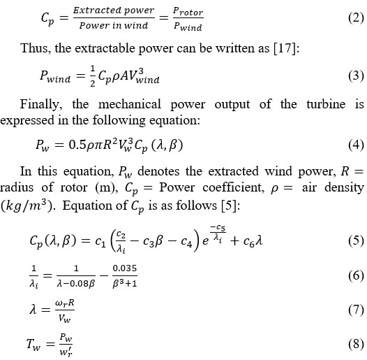
Here, represents the torque of the turbine, pitch angle (degree), rotor speed (rad/s), toward turbine’s characteristic coefficients ( ) [5,17-18]. represents the tip speed ratio.
Figure 1 shows the characteristic graph. The graph is established for a diverse value of from Equation (5). Here, the optimum value for and for the optimal value of [5].
The maximum power point (MPPT) of the PMSG system is displayed in Figure 2 [5].
3. Power System Model
Figure 3 represents a power system model employed to analysis the transient stability of the system. The control strategy and construction of the system are portrayed in the diagram. The system model consists of a WT, a PMSG, a DC/AC, and an AC/DC inverter system. It is a 20 MW system connected to an infinite bus by a 1.8 kV/33 kV transformer. A load of 9 MW and 6 MVAR is attached to the system through the transformer. All the necessary parameters of PMSG system are taken from Ref. [19].
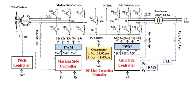
Figure 4: Arrangement of PMSG system.
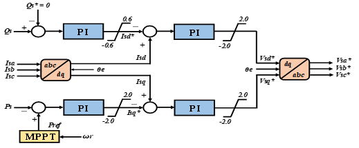
Figure 5: Machine side controller.
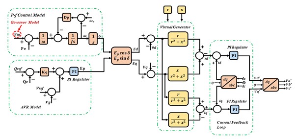
Figure 6: Proposed VSG control strategy.
4. PMSG Model and Control System
PMSG is a VSWT generator system furnished with a comprehensive power electronic frontier. Figure 4 portrays the control system and design layout of a PMSG-based VSWT. The total system consists of PMSG, WT with drive train models, pitch angle control system, VSG controlled grid side inverter (GSI), and machine side converter (MSC). Two levels of IGBT are used here to build both the converter circuits used in the system. The MSC and the VSG controller are in charge of controlling the converters. The MSC has a direct link to the stator terminal of PMSG. The GSI system is connected to the grid using step-up transformers. The analysis in this study makes use of the already-available PMSG model from the PSCAD library [20].
The comparator circuit block controls the DC chopper circuit that is included in the DC-link protection controller system. The comparator initiates the DC chopper circuit when the DC-link voltage ( ) is ≥ 1.05 pu and consequently, safeguards the DC-Link system. This system utilizes the PWM strategy, and for both converters, the carrier frequency of 3.0 kHz and the rated of 3.0 kV are chosen [21].
4.1. Machine Side Controller
The MSC converts the entire three-stage, unregulated AC voltage that the PMSG produces into DC voltage. Figure 5 represents the control scheme for the MSC arranged by using four PI controllers. There are two loops in the controller mechanism. The upper loop is employed for reactive power, and the lower loop is responsible for the active power. In the PMSG, the q-axis current ( ) controls the active power ( ), and the current of the d-axis ( ) controls the reactive power ( ).
The reference active power ( ) is determined utilizing the MPPT algorithm. The procedure is narrated in section 3 of this paper. The reference reactive power ( ) has been set to zero in order to execute the operation regarding the unity power factor [21].
4.2. Proposed VSG Control Strategy
This section briefly portrays the proposed controller of VSG. Figure 6 addresses the generally introduced VSG control procedure. The proposed control framework incorporates a governor model, an AVR model, and a virtual generator model along with a current feedback loop.
4.3. VSG Model
The impedance model for VSG is shown in Figure 7. The armature resistance and the synchronous reactance of the generator are represented by r and x, respectively. The field windings generate an electromotive force which is designated by and δ denotes the load angle between the rotor and the grid.
The voltage of the grid and its prolongation toward axis d and q axis is expressed by , , and respectively. Similarly, and characterize the armature currents for the axis d and q, respectively and are illustrated in the subsequent equation.
In order to regulate the command regarding the current inverter system, the above-described parameters are occupied.
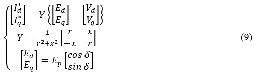
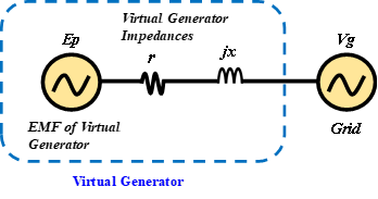
Figure 7: VSG impedance model.
4.4. Active Power-Frequency Control Strategy
The grid frequency can be managed by utilizing the VSG control system. VSG control in the inverter circuit empowers the required control for primary frequency by coordinating a suitable measure of power via inertial feedback. The VSG algorithm obtains the load angle (δ) with the utilization of the swing equation. The swing equation depends on the changes in active power. The equations stated in this section represent the principal contraption of the VSG [22-23].
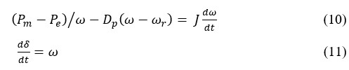
Similarly, as a SG, the reference active power and the instantaneous active power are addressed by Pe and Pm successively. Here, the droop constant is represented by Dp, J represents the inertia, angular frequency is represented by ω, and the reference angular frequency by ωr accordingly. Besides, a governor model is also employed to carry out the task of controlling the input power directive according to frequency alteration. Figure 8 shows the governor model.

Figure 8: Governor Model.
4.5. AVR Model
By utilizing a fundamental excitation strategy of the SG, the reactive power-voltage regulatory system is possible to plan. Figure 6 portrayed the control strategy. The following equation contemplates the resulting voltage:
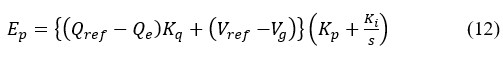
Qref denotes the reference value of reactive power, whereas Qe stands for the instantaneous reactive power, the reference voltage is expressed by Vref, and the terminal voltage is expressed by Vg, respectively. Kq represents droop control for the reactive power. Kp and Ki, respectively, are used to denote the proportional and integral gains of the PI controller.
4.6. Current Feedback Loop
As depicted in Figure 6, a pair of PI regulators make up the current feedback loop. The mentioned PI regulators remunerate the current of the axis d and q to produce the reference value for d and q axis voltage. The fundamental inclination of the alteration is acquired via the grid network.
5. FRT Requirement for Wind Power Generation
Power quality, reliability, and the electrical grid’s stability are just a few of the issues that have arisen owing to the massive incorporation of large-scale wind energy generation facilities into the utility network. The transmission system operators (TSOs) have been urged to update grid codes to accommodate the technical specifications of wind power facilities as a result of this integration [24]. Wind generators having an FRT facility is one of the crucial requirements of WF grid codes which implies that ordinary power production ought to be continued rapidly immediately after the apparent grid voltage has been retrieved after facing disruption in the power production.
FRT prerequisites for the WFs are illustrated in Figure 9 [25]. Suppose there is a voltage dip situation in the system within the predetermined RMS value and the duration of the voltage drop is within the predefined value. In that case, the WFs must stay in operation with the grid. The conditions are illustrated in Figure 9.
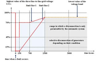
Figure 9: FRT requirement for WF.
Every WT inside the WF hereby remains in operation without any trip on the off chance that the connection point’s voltage recuperates the appraised voltage by 90% in 1.5 seconds after the voltage dip situation. This guarantees that wind generation is not interrupted by routinely cleared defects. Utilities also stipulate that wind turbines have voltage stability for set amounts of time and that they must be able to maintain the grid during fault incidents.
6. Simulation Results and Discussions
The power system model presented in Figure 3 was employed to conduct the simulation work utilizing the PSCAD/EMTDC software. As depicted in Figure 3, a 3LG fault is applied near the inverter of the PMSG to investigate the system’s transient stability. The fault happened at 5.0 s, and lasts for 0.05 s. The CB opens at 5.1 s and then closes once more at 6 s based on the supposition that the fault condition has disappeared.
The fault and CB conditions are presented in Figure 10. The total time span of the simulation is considered as 10 s due to transient stability analysis and system frequency is 50 Hz.

Figure 10: 3LG fault conditions.
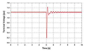
Figure 11: Terminal voltage response.
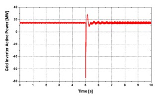
Figure 12: Active power response of grid inverter.
On the assumption that the wind speed wouldn’t change for a short while, the applied wind speed to PMSG is maintained constant under rated conditions. Figure 11 through 14 presents the findings from the simulation work. The terminal voltage response of PMSG is illustrated in Figure 11. Initially stable, a voltage dip happened during the fault time. However, the terminal voltage quickly returns to the nominal value after the fault duration and follows the grid code discussed in Section 5. This graph clearly indicates the FRT capability of the proposed VSG control approach.
Figures 12 to 13 show that the PMSG’s active and reactive power responses are stable following the fault. Finally, Figure 14 presented the PMSG’s rotor speed response. The rotor speed is oscillating more between 5.0 s to 6.0 s. This is because, the severe fault occurs at 5.0 s. Even though, the response is fluctuating during the fault period, the rotor speed is stable after the fault clearance.
Therefore, it may be said that the proposed VSG technique has shown significant effectiveness and efficiency in stabilizing the PMSG system during severe fault periods along with enhancing the FRT capability.
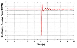
Figure 13: Reactive power response of grid inverter.
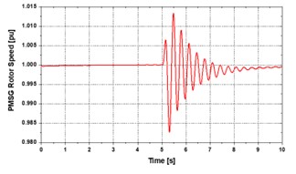
Figure 14: Rotor speed response of PMSG.
7. Conclusion
The most sustainable and renewable source of electricity is still wind. However, the system must be able to sustain voltage dip situations brought on by system faults according to the current WF grid code, which is impossible with a conventional control mechanism but with a VSG control approach. This paper proposes and analyzes a VSG control mechanism for a PMSG-based wind turbine to enhance the system stability and FRT capability of a grid-connected wind energy generation system. All details of the proposed approach, including diagrams along with the related simulation findings, are provided in this paper. According to the simulation results, the system can withstand a severe fault event (3LG fault).
Acknowledgment
This study has been conducted based on the research fund received from American International University-Bangladesh (AIUB).
- Global Wind Report 2022, Global Wind Energy Council (GWEC), 2022, (https://gwec.net/global-wind-report-2022/, Accessed on: 30 June, 2022).
- Muyeen, S.M., Tamura, J. and Murata, T., Stability Augmentation of a Grid Connected Wind Farm, Springer-Verlag, London, 2009.
- Liu, Zhongyi & Liu, Chongru & Li, Gengyin & Liu, Yong & Liu, Yilu, “Impact Study of PMSG-Based Wind Power Penetration on Power System Transient Stability Using EEAC Theory,” Energies, 8(12), 13419–13441, 2015, doi:10.3390/en81212377.
- A. A. MERI, Y. AMARA and C. NICHITA, “Impact of Fault Ride-Through on Wind Turbines Systems Design,” in 2018 7th International Conference on Renewable Energy Research and Applications (ICRERA), 567–575, 2018, doi:10.1109/ICRERA.2018.8566910.
- M. Rosyadi, A. Umemura, R. Takahashi, J. Tamura, N. Uchiyama, and K. Ide, “Simplified Model of Variable Speed Wind Turbine Generator for Dynamic Simulation Analysis,” IEEJ Transactions on Power and Energy, 135(9), 538–549, 2015, doi:10.1541/ieejpes.135.538.
- R. C. Pawaskar and T. B. More, “Improvement in low voltage ride through capability of PMSG based wind energy system,” in 2016 International Conference on Global Trends in Signal Processing, Information Computing and Communication (ICGTSPICC), 444–447, 2016, doi:10.1109/ICGTSPICC.2016.7955342.
- M. Jahanpour-Dehkordi, S. Vaez-Zadeh and J. Mohammadi, “Development of a Combined Control System to Improve the Performance of a PMSG-Based Wind Energy Conversion System Under Normal and Grid Fault Conditions,” IEEE Transactions on Energy Conversion, 34(3), 1287–1295, Sept. 2019, doi:10.1109/TEC.2019.2912080.
- E. Sathya and P. Maruthupandi, “Enhancement of Low Voltage Ride Through Capability for PMSG Based Wind Energy Conversion System With Super Capacitor,” in 2018 4th International Conference on Electrical Energy Systems (ICEES), 57–60, 2018, doi:10.1109/ICEES.2018.8443259.
- H. Fang, X. Zhang and Y. Wei, “Supercapacitor Energy Storage System based Coordinative Low-Voltage-Ride-Through Control for Wind Energy Conversion System, ” in 2021 24th International Conference on Electrical Machines and Systems (ICEMS), 276–280, 2021, doi:10.23919/ICEMS52562.2021.9634199.
- Y. Peng et al., “Coordinated Control Strategy of PMSG and Cascaded H-Bridge STATCOM in Dispersed Wind Farm for Suppressing Unbalanced Grid Voltage,” IEEE Transactions on Sustainable Energy, 12(1), 349–359, Jan. 2021, doi:10.1109/TSTE.2020.2995457.
- V. Ramachandran, A. S. Perumal, N. Lakshmaiya, P. Paramasivam, and S. Dhanasekaran, “Unified Power Control of Permanent Magnet Synchronous Generator Based Wind Power System with Ancillary Support during Grid Faults,” Energies 2022, 15(19), 7385, doi:10.3390/en15197385.
- J. X. Jin, R. H. Yang, R. T. Zhang, Y. J. Fan, Q. Xie, and X. Y. Chen, “Combined low voltage ride through and power smoothing control for DFIG/PMSG hybrid wind energy conversion system employing a SMES-based AC-DC unified power quality conditioner,” International Journal of Electrical Power & Energy Systems, 128, 106733, Jun. 2021, doi:10.1016/j.ijepes.2020.106733.
- S. Alepuz, A. Calle, S. Busquets-Monge, S. Kouro and B. Wu, “Use of Stored Energy in PMSG Rotor Inertia for Low-Voltage Ride-Through in Back-to-Back NPC Converter-Based Wind Power Systems,” IEEE Transactions on Industrial Electronics, 60(5), 1787–1796, May 2013, doi:10.1109/TIE.2012.2190954.
- Z. Liu, C. Liu and G. Li, “Power coordinated control of wind turbines with permanent magnet synchronous generator for low voltage ride through,” in IEEE PES General Meeting | Conference & Exposition, 1–5, 2014, doi:10.1109/PESGM.2014.6939204.
- H. Bevrani, T. Ise, and Y. Miura, “Virtual synchronous generators: A survey and new perspectives,” International Journal of Electrical Power & Energy Systems, 54, 244–254, 2014, doi:10.1016/j.ijepes.2013.07.009.
- K. Shi, W. Song, P. Xu, R. Liu, Z. Fang, and Y. Ji, “Low-Voltage Ride-Through Control Strategy for a Virtual Synchronous Generator Based on Smooth Switching,” IEEE Access, 6, 2703–2711, 2018, doi:10.1109/ACCESS.2017.2784846.
- Singh, Mohit & Santoso, Surya, Dynamic Models for Wind Turbines and Wind Power Plants, Wind Power: Systems Engineering Applications and Design Models, 2011.
- Matlab Documentation Center, (http://www.mathworks.co.jp/jp/help/, Accessed on: 20 December, 2016).
- Y. Errami, M. Ouassaid, M. Maaroufi, Control of a PMSG based Wind Energy Generation System for Power Maximization and Grid Fault Conditions, Energy Procedia, 42, 220–229, 2013, doi:10.1016/j.egypro.2013.11.022.
- PSCAD/EMTDC User’s Manual (1994), Manitoba HVDC Research Center, Canada.
- Y. Hirase, K. Abe, K. Sugimoto, and Y. Shindo, “A grid-connected inverter with virtual synchronous generator model of algebraic type,” Electrical Engineering in Japan, Wiley Online Library, 184(4), 10–21, 2013, doi:10.1002/eej.22428.
- J. Meng, Y. Wang, J. Peng, L. Xu, and J. Yin, “Flexible Virtual Synchronous Generator Control for Distributed Generator with Adaptive Inertia,” Electric Power Components and Systems, 47(1-2), 128–140, 2019, doi:10.1080/15325008.2018.1563958.
- J. Alipoor, Y. Miura and T. Ise, “Power System Stabilization Using Virtual Synchronous Generator with Alternating Moment of Inertia,” IEEE Journal of Emerging and Selected Topics in Power Electronics, 3(2), 451–458, 2015, doi:10.1109/JESTPE.2014.2362530.
- O. P. Mahela, N. Gupta, M. Khosravy and N. Patel, “Comprehensive Overview of Low Voltage Ride Through Methods of Grid Integrated Wind Generator,” IEEE Access, 7, 99299-99326, 2019, doi:10.1109/ACCESS.2019.2930413.
- E. ON NETZ GmbH (2006) Grid Connection Regulation for High and Extra High Voltage. E. ON NETZ GmbH, Essen, Germany.