Condition Assessment of Medium Voltage Assets: A Review
 , Joaquín Caicedo 2, Miguel Mamaní 1, David Romero Quete 3, Andrés Cerón Piamba 4, Diego García Gómez 4, Guillermo Aponte Mayor 4, José Caicedo Erazo 4, Wilmar Moreno López 5, Edward Jay 5, Andrés Romero Quete 1
Adv. Sci. Technol. Eng. Syst. J. 8(5), 35–54 (2023);
 DOI: 10.25046/aj080505
Condition assessment of medium voltage assets is essential to ensure reliability and cost-effective operation of power distribution networks. This article presents a literature review of condition assessment of medium voltage assets related to a distribution system in a non-interconnected zone in Colombia, namely, power transformers, photovoltaic systems, switchgear, lines and cables, and instrument transformers. Advanced search rules are formulated to obtain bibliographic records of relevant academic literature from the database Scopus. The retrieved data are analyzed quantitatively to provide insights on the current state of research on the topic. Next, the most relevant academic papers for each medium voltage asset are selected and analyzed in a critical review along with more diverse literature including standards, technical reports, and white papers obtained through complementary searches. The results of the review show that several approaches have been formulated for condition assessment of medium voltage assets, ranging from traditional diagnostic methods to advanced artificial intelligence-based approaches. Moreover, research on some assets is already mature including power transformers, and photovoltaic systems, whereas other assets have been incipiently studied such as distribution and instrument transformers. Therefore, the need for deeper condition assessment research for these critical assets is highlighted. Research gaps are identified in the standardization and integration of condition assessment tools for distribution system operators.
1. Introduction
This paper extends a work presented in IEEE Biennial Congress of Argentina, ARGENCON 2022, [1]. This extended review covers other important Medium-Voltage (MV) assets operating in distribution networks. The review is a key component of a government-funded research project in Colombia aimed at implementing a digital platform for asset management of components at the archipelago San Andrés, Providencia, and Santa Catalina distribution network, in agreement with ISO 55000 [2].
In the islands, the distribution network consists of distributed generators (diesel and solar) which supply power to MV feeders at 34,5 kV and 13,2 kV, and Low-Voltage (LV) end customers at 208/120 V. The main assets in the distribution network are:
- Power Transformers (PT)
- Photovoltaic (PV) systems
- Distribution Transformers (DT)
- MV switchgear
- MV lines and cables
- Instrument Transformers (IT)
In this context, this paper offers a review of the main technical aspects related to condition assessment of distribution network assets. The study focuses on a non-interconnected grid.
The paper is structured as follows. The next subsections describe the methodology adopted for the literature review and the taxonomy to structure the analysis. Section 2 introduces the review of condition assessment of PT. Similarly, Section 3 reviews condition assessment of PV systems, followed by the review of DT, switchgear, lines and cables, and IT, in Sections 4 to 7. Section 8 outlines the discussion of results. Section 9 explores prospects for future research. Section 10 states the conclusions of the paper.
1.1. Methodology for the literature review
The literature review methodology is based on the Preferred Reporting Items for Systematic Reviews and Meta-Analyses (PRISMA) [3]. The advanced search rules illustrated in Figure 1, are applied in titles, abstracts, and keywords of the citation database Scopus to identify the most relevant literature related to condition assessment of MV assets. On the one hand, concepts related to condition assessment are included in each search rule and synonyms and associated concepts are also used according to Table 1. On the other hand, seven individual search rules are formulated to consider the most relevant assets of the distribution network in San Andrés Islands, i.e., (1) PT, (2) PV systems, (3) DT, (4) switchgear, (5) lines and cables, and (6) IT. In this case, synonym keywords and compound search formulas are defined according to Table 2.
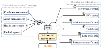
Figure 1: Advanced search rules applied in Scopus on April 1st, 2023.
Table 1: Set of synonym keywords related to condition assessment concepts.
| Concept | Set of synonym keywords |
| Condition assessment | “condition assessment” OR “condition monitoring” OR “remaining useful life” OR “performance index” |
| Asset management | “asset management” |
| Health assessment | “health monitoring” OR “health index” |
| Fault diagnosis | “failure detection” OR “failure diagnosis” OR “fault detection” OR “fault diagnosis” |
Table 2: Set of synonym keywords and compound search formulas for MV assets.
| Asset | Set of synonym keywords / compound searches |
| PT | “power transformer” |
| PV system | “photovoltaic generat*” OR “pv generat*” OR “photovoltaic system” OR “pv system” |
| DT | “distribution transformer” |
| Switchgear | switchgear OR “power circuit breaker” OR disconnector OR recloser OR (“circuit breaker” W/2 (distribution OR OR medium-voltage OR mv)) |
| Line / cable | (distribution OR medium-voltage OR mv) W/2 (line OR cable) |
| IT | “instrument transformer” OR “current transformer” OR “voltage transformer” |
Figure 1 shows that the concepts related to “condition assessment” are merge with an “OR” operator, i.e., the terms are considered synonyms and any of them is useful to retrieve the bibliographic records. Moreover, “condition assessment” concepts and “distribution network assets” are associated with the operator “W/2”, i.e., one of the terms can be found within a distance of two words from the other. For instance, if “condition assessment” (or “asset management”, or “health assessment”, or “fault diagnosis”) appears in the tittle, abstract or keywords of a bibliographic record, and “power transformer” is found in the same record within a distance of two words, then the record is retrieved.
The number of records retrieved using the search rules on April 1st, 2023, are reported in Table 3. Results show extensive research related to strategic assets such as PT and PV systems, where several recently published literature reviews are found. However, limited research has been performed on condition assessment of other relevant assets such as DT and IT. In this context, this paper offers an overview of condition assessment for both widely and incipiently studied assets. It analyzes previously less explored aspects in detail to provide a comprehensive review of key technical considerations.
Table 3: Number of records retrieved with the proposed search rules.
| Search rule | Jour. articles | Conf. papers | Reviews | Others | Total |
| PT | 349 | 592 | 29 | 6 | 976 |
| PV system | 124 | 91 | 15 | 7 | 237 |
| DT | 12 | 37 | 2 | 0 | 51 |
| Switchgear | 26 | 53 | 3 | 0 | 82 |
| Line / cable | 42 | 68 | 2 | 1 | 113 |
| IT | 6 | 20 | 0 | 0 | 26 |
Figure 2 presents the evolution from 2003 to 2022 of the number of publications retrieved using each search rule. The figure shows an increasing trend across nearly all topics, with a particular emphasis on PV systems, which has seen a significant surge in publications over the last five years. A significant increase occurred in PT condition assessment from 2006 to 2008, and then the trend is slightly positive. Other moderately studied topics show an increasing interest such as lines and cables, switchgear, and DT. Finally, research is very incipient in IT condition assessment.
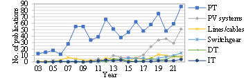
Figure 2: Publications related to condition assessment of MV assets over time.
A set of relevant publications are selected from the retrieved bibliographic records to perform the critical review of each asset. In the case of extensively studied topics, i.e., PT, and PV systems, the analysis is based on recently published reviews and a limited selection of additional relevant publications to observe aspects that required further analysis. The review of the remainder assets, i.e., DT, switchgear, lines and cables, and IT, is based on relevant publications selected by reading and assessing titles, abstracts, and conclusions of the retrieved bibliographic records. Moreover, references are complemented with related standards, technical reports, and white papers.
1.2. Taxonomy for condition assessment in distribution networks
The following structure is adopted to analyze each asset:
- A short description of the main asset’s components, subsystems and features is given.
- Fault diagnosis and condition assessment approaches for each asset are described and the references are classified according to the type of test and diagnostic technique.
- Indices to monitor the condition of assets are analyzed.
The following subsections provide a broader description of the aspects covered in fault diagnosis and condition assessment of the MV assets, along with a taxonomy of test types and diagnostic techniques. Aspects related to indices are also introduced.
a) Fault diagnosis and condition assessment
Fault diagnostic and condition monitoring techniques for power assets is a wide and very dynamic research and innovative field. The variety of tests and techniques ranges from traditional and widely accepted methods, to advanced and not completely validated approaches. The main differences are based on the possibility that offers the technique to obtain a diagnosis with the asset in-service or off-service, i.e., the asset operating status. The diagnostic test nature differs according to the parameter to be analyzed, e.g., gas chromatography, which is a method from analytical chemistry commonly used to assess the insulating oil condition. In addition to chemical tests, mechanical or electrical tests can also be applied to analyze other oil features.
Once the tests or inspections have been carried out on the asset, the acquired data must be analyzed for diagnosis. This analysis can be based on expert judgment, who, like doctors in medicine, examine the data and offer a conclusion on the health status or presence of failures in the asset. This type of expert knowledge-based approaches also includes computational methods based on rules such as expert systems, and fuzzy logic.
Alternatively, analytical methods are applied by inferring a set of mathematical equations to model the phenomena involved in the asset condition as close to reality as possible. Thus, analytical models offer very accurate diagnostics, but require comprehensive understanding of the asset, in terms of specific components and operating modes, as well as the status of asset parameters.
Finally, the data acquired from tests can also be analyzed automatically with Artificial Intelligence (AI)-based techniques including Support Vector Machines (SVM), decision trees, and Artificial Neural Networks (ANN), among others. AI-based approaches provide flexible and efficient performance, which is of especial interest in large and complex systems with thousands of assets. However, these AI-based methods, also referred to as data-driven approaches, need large amounts of training and validation data, and are prone to underfitting and overfitting.
Figure 3 summarizes the process described above for fault diagnosis and condition assessment, i.e., 1) data from tests or inspections are acquired, and 2) diagnostic techniques are applied for data analysis. The figure also depicts the taxonomy of tests and diagnostic techniques discussed earlier. This taxonomy is used throughout the comprehensive review to classify tests and methods reported in the literature.
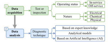
Figure 3: Taxonomy for fault diagnosis and condition assessment techniques.
b) Indices for condition assessment
In the international standard ISO 55000 [2], the main indices related to condition assessment of power assets are the Health Index (HI), consumed life and remaining life indices, performance indices, among others. Therefore, these indices are identified and described in each asset review.
2. Power Transformers (PT)
PT play a crucial role in power systems due to their strategic significance and higher costs compared to other power assets. In distribution networks, PT are usually referred to as primary DT, which connect MV networks to distributed generators, or, in interconnected systems, with High-Voltage (HV) transmission networks. Hence, the PT failure represents the impossibility of providing many customers with electrical energy. In brief, a PT comprises five subsystems. The main subsystem is the Active Part (AP) made up of windings, core, insulating paper, clamp structures, yoke, oil, and a tank containing the mentioned elements. The remainder four subsystems are (i) Bushings (BH) and terminals, (ii) On Load Tap Changer (OLTC), (iii) Conservator Tank (CTk) and breather, and (iv) the Cooling System (CS) made up of fans, pumps, controls, and radiators.
There is great interest in researching techniques for PT condition assessment. According to Table 3, a significant number of 976 bibliographic records were obtained using the search rule reported in Section 1.1. Among those publications, comprehensive and recently published literature reviews are found, e.g., [4–10]. Therefore, the following analysis summarizes the key findings of those reviews. Also, the review is complemented with standards [11–15], and selected papers [16–48].
2.1. Fault diagnosis and condition assessment of PT
Condition monitoring is an essential aspect of PT management. It involves the use of sensors and other monitoring devices to measure several parameters, such as temperature, oil level, and Partial Discharges (PD), which allows for detecting faults or changes in the asset performance. Advanced methods such as Dissolved Gas Analysis (DGA) are also employed to track the condition of transformer insulation systems. These methods allow early detection of faults and diagnosis of the PT status to take proper maintenance actions, thus reducing service interruptions and economic losses associated with its unavailability. Data sources, in both fault diagnosis and condition assessment, are acquired from the PT (primary source), power system, and environment. For this purpose, the main tests for monitoring PT parameters by subsystem and type are reported in Table 4.
From the tests in Table 4, it is worth noting that in-service condition monitoring allows continuous evaluation of the operation and offers the possibility of assessing the states that may impact the lifespan of the PT, whereas off-service tests require disconnecting the unit from the power grid, limiting its use to maintenance scenarios, planned inspections, or when there is a direct suspicion of failure.
Table 4: Classification of tests on PT and diagnostic techniques.
|
|||||||||||||||||||||||||||||||||||||||||||||||||||||||||||||||||||||||||||||||||||||||||||||||||||||||||||||||||||||||||||||||||||||||||||||||||||||||||||||||||||||||||||||||||||||||||||||||||||||||||||||||||||||||||||||||||||||||||||||||||||||||||||||||||||||||||||||||||||||||||||||||||||||||||||||||||||
Regardless the type of applied tests mentioned above, resulting data must be processed to generate information about the asset status. Consequently, diagnostic techniques are applied to assess the condition of PT and find any defects or malfunctions. For instance, these techniques include Frequency Response Analysis (FRA), which can detect winding deformation and core movement, or the analysis of tan d, capacitance, and dielectric response measurements, among others, which can identify insulation degradation. In this regard, several diagnostic techniques have been proposed and the most relevant are also reported in Table 4 following their related tests.
Furthermore, analysis of data from traditional tests to diagnose the PT electrical performance, for instance, excitation current, power factor, and winding resistance, has rarely been addressed in recent research because of its straightforward interpretation and broad understanding and acceptance by PT managers. In contrast, most of the current research on PT condition assessment is focused on approaches or methodologies to improve the interpretation of the results, especially from FRA, Dielectric Frequency Response (DFR), DGA, acoustic signals, PD detection, and indirect Degree of Polymerization (DP) estimation. These recent approaches and methodologies are aimed at overcoming the difficulties related to accuracy, uncertainty, interpretation, ambiguity, and discrepancies related to traditional and standard diagnosis.
For instance, in FRA and DFR, an option consists of comparing the magnitude and phase angle of the frequency response on a polar plot, which can then be analyzed by an expert. Alternatively, numerical models are used to simulate the behavior of transformers under different conditions. For instance, the effects of winding deformation, core movement, moisture content in oil and other defects on the transformer frequency response can be considered with these models. The simulated and measured frequency response are then compared to detect the presence of defects. A third alternative for analyzing the results of FRA and DFR is the use of machine learning techniques including decision trees, and ANN to identify patterns and predict the likelihood of defects or failures.
Similarly, DGA, which aims at identifying electrical faults, can be conducted with traditional analysis using Rogers ratio, key gas, Dornenburg ratio, Duval triangle and pentagon. Also based on expert knowledge, fuzzy logic allows the diagnosis of multiple failures, a more realistic representation, and quantification of the probability/severity of each damage. AI-based techniques are also applied to DGA interpretation. For instance, the use of ANN has the benefit of not requiring experts for the interpretation of DGA Approaches based on AI offer new possibilities in the application of DGA due to their automatic learning and data analysis capabilities. These approaches recognize different patterns of gas concentrations, which indicate the type of failure or problems within the transformer through the processing of large volumes of historical DGA data. These data are automatically identified and classified in real time or in certain time intervals, allowing for improvement and effectiveness in the early detection and diagnosis of failures. AI can recognize complex patterns and sudden deviations in gas concentration that are not easily noticed by experts. It is crucial to continue improving AI-based techniques to incorporate new research findings, such as the C2O/CO ratio, for identifying failure patterns in the insulating paper.
The discussion above demonstrates that research on condition assessment of PT is a very important and fertile area of work, especially with the emergence of powerful AI-based tools to analyze large amounts of data that this type of asset generates.
2.2. Indices for condition assessment of PT
A crucial indicator in asset management of PT is the Health Index (HI) because it is required to perform fault diagnosis, life prediction and risk assessment. A PT-HI is a quantitative indicator that considers the results of asset performance observation, on-site inspections, and laboratory tests, to efficiently manage the asset. In 2017, a complete analysis of the main PT-HI calculated using mathematical equations/algorithms or expert judgment is reported in [10]. Such a paper analyzes the period 2008-2017, including the first approach published in 2008 [42]. Most of the expressions are based on the weighted summation of multiple input parameters, i.e., multi-criteria methods. In general, ranges of input parameters (collected through tests discussed above) are based on limits recommended by IEC and IEEE standards, and expert knowledge from utilities. The number of input parameters and weights varies from approach to approach. A complete list of the most used parameters is reported in [10].
Advanced techniques for PT-HI calculation are based on fuzzy logic [43–46], and ANN [47,48]. From a practical point of view, utilities prefer weighted summation approaches because of their simplicity and higher flexibility compared with advanced methods that require specialized knowledge to implement modifications.
3. Photovoltaic (PV) systems
PV systems are increasingly penetrating distribution networks as an alternative means of producing electricity motivated by the necessity of more sustainable energy sources than fossil fuels. PV systems exhibit rapid expansion within the realm of renewable energy technologies, primarily attributed to the enduring and readily accessible source of solar energy at no cost [49]. According to the International Energy Agency, the global PV capacity grew from 50 MW in 1990 to 946 GW in 2021 [49,50].
Depending on usage, PV systems can operate stand-alone used for remote power or backup applications, or grid-connected to complement the power provided to an installation from the utility grid [51]. Both stand-alone and grid-connected PV systems are mainly made up of (i) an array of solar PV panels which convert sunlight into electricity, (ii) inverters to transform DC into AC power, (iii) protection and switching equipment, (iv) supporting structure and mounting racks, (v) combiner boxes, conductors and grounding, (vi) energy meters and, optionally, (vii) an energy storage system and charge controller [49,51]. These components are exposed to deterioration and failures that make essential the use of condition assessment methods to guarantee sustainable techno-economic operation of PV systems. In the following sections, the aspects above are discussed based on the retrieved literature.
The results obtained with the search rule formulated in Section 1.1 for PV systems show that there is extensive research on the topic, i.e., 237 bibliographic records were retrieved including 15 literature reviews (see Table 3). Moreover, Figure 2 demonstrates an apparent increasing interest on the topic in the last few years. Therefore, emphasis is placed on the analysis of recent literature reviews [52–68]. In addition, the literature is complemented with standards [69–71], selected papers [72–76], and reports [77].
3.1. Fault diagnosis and condition assessment of PV systems
Condition assessment of PV systems is achieved by monitoring performance parameters of the components described above. For instance, these parameters include the operating voltage, current, and power output, which mainly depend on the proper operation of the array of solar PV panels, inverters, and the energy storage system. Integrity of combiner boxes, grounding, and insulation resistance must be also verified for condition assessment. These parameters are measured using instruments such as PV testers, solar power meters, insulation testers, battery analyzers, among other devices. In addition, testing procedures must be applied during installation, i.e., at commissioning, and regularly during the lifespan of the PV system. Standard and widely used and validated testing procedures for PV systems, as well as indication on suitable measurement instruments, are outlined by IEC 62446-1:2016 [69], and IEEE Std 1547-2018 [70], for grid-connected PV systems, and IEEE Std 1526-2020 [71], for stand-alone PV systems. Table 5 summarizes the tests applied on PV systems found in the literature, shows the corresponding diagnostic techniques, and indicates the PV subsystem involved in each test and the measured parameters.
Testing procedures described in standards include continuity verification of conductors and grounding, polarity check in combiner boxes and conductors, open circuit voltage, and short circuit and operational currents in the PV array, which are relevant parameters to monitor the correct operation of PV systems [69–71]. Tests are also conducted on the energy storage system such as usable battery capacity, recovery, and battery charge tests [71].
Additional testing procedures with demanding requirements for result analysis are described in the literature such as I-V curve-based approaches to study PV system performance from its I-V characteristic [53,57,73,74]. Other investigations use infrared thermography to detect hot spots in PV systems [56,62,64,69]. Moreover, flash, electroluminescence, and X-ray tests are employed to find defects in PV arrays [59,60,72]. It is worth noting that the I-V characteristic can be analyzed indirectly using thermography, flash, electroluminescence, and X-ray because there is a relation between hot spots and defects found with those tests and the voltage and current performance of the PV system. Tests and simulations are also performed for model parameter identification which is mainly intended for simulation, optimization of PV system performance, and energy production forecasting [55,65]. Moreover, modeling, simulation, and testing of faults have been widely studied. For instance, [52] presents an extensive overview of models to analyze DC faults in PV systems. The work in [53,63] extend the overview of electrical faults on the PV array, inverters, and the AC side of PV systems. In addition, [54,66] analyze not only electrical faults, but also physical, e.g., damage, cracks, and deterioration in PV panels, and environmental faults, e.g., temporary, and permanent partial shading. As an alternative to detailed modeling and simulation, PV and solar emulators are also available to perform a variety of tests [73,74]. This system type enables the emulation of faults within PV systems, as well as the evaluation of performance by means of analyzing the I-V curve.
Table 5: Classification of tests on PV systems and diagnostic techniques.
|
|||||||||||||||||||||||||||||||||||||||||||||||||||||||||||||||||||||||||||||||||||||||||||||||||||||||||||||||||||||||||||||||||||||||||||||||||||||||||||||||||||||||||||||||||||||||||||||||||||||||||||||||||||||||||||||||||||||||||||||||||||||||||||||||||||||||||||||||||
After PV systems are tested, different diagnostic techniques are applied to analyze results. These techniques can be classified according to the categories identified in Section 1.2 (see Figure 3), i.e., expert knowledge, analytical models, and based on AI. Table 5 also includes the classification of tests and diagnostic techniques according to the taxonomy defined in Figure 3.
A first set of approaches based on expert knowledge are standards, and manufacturer recommendations to assess electrical, mechanical, and electromechanical performance of PV systems [69–71]. In these methods, expert knowledge is required to apply tests using measurement instruments and provide a performance assessment based on the parameters established by standards. Furthermore, I-V curve tests are also analyzed through expert knowledge using handcrafted diagnosis [57], monitoring real-time difference with respect to a reference I-V curve [54,57], and using PV and solar emulators [73,74]. Also, expert systems used for interpretation of infrared thermography [62], and fuzzy logic for fault diagnosis in PV systems require expert knowledge [65].
Analytical models proposed for PV system analysis include, for instance, equations formulated to compute usable battery capacity, recovery, and battery charge in stand-alone applications [71]. Other examples include the analytical approach for model parameter identification [55,65], and the model-based difference for fault diagnosis [54], where monitored parameters of PV systems are compared with a modeled and theoretical reference to identify deviations from the correct operation.
Approaches based on AI techniques have been extensively used in the last few years. For instance, machine learning tools such as SVM, ANN, Generative Adversarial Networks (GAN), transfer learning, and decision trees are used for automatic analysis of images in infrared thermography [56,62,64,69], flash, electroluminescence, and X-ray [59,60,72], and in fault diagnosis applications [52–54,56,58,61,63,66,73,74]. Similarly, deep learning tools such as Deep Belief Networks (DBF), Long Short-Term Memory (LSTM), and Convolutional Neural Networks (CNN), have been also applied recently because of their extended capabilities for image analysis. All these AI techniques mentioned above usually require a previous step of feature extraction where statistics and signal processing techniques, e.g., Wavelet Transform (WT), and Fast Fourier Transform (FFT), are applied.
3.2. Indices for condition assessment of PV systems
In the literature, performance indices are offered for health and condition monitoring of PV systems. For instance, the world-wide association SolarPower Europe made up of hundreds of companies and policymakers from the solar sector, proposed best practice guidelines for asset management of PV projects [77]. Within the scope of these guidelines, Key Performance Indicators (KPI) are suggested to achieve technical asset management of PV power plants, e.g., specific and reference yield, performance ratio, energy performance index, among others. Moreover, equipment KPI are also indicated in the guidelines such as inverter specific energy losses, Mean Time Between Failures (MTBF), etc. Likewise, energy metrics are proposed in [76] to assess the behavior of PV systems. These metrics comprise daily and monthly energy output, array energy yields, PV array and system efficiency, capacity utilization factor, and life cycle conversion efficiency.
Furthermore, indices to analyze condition from the degradation perspective are also found in the literature. In this context, [67,68] offer a comprehensive review of degradation rates of PV systems around the world, and factors and parameters involved in the degradation process such as corrosion, encapsulant discoloration, and light and elevated temperature induced degradation. Similarly, [75] studies a health monitoring method based on the study of I-V curves and degradation modes of the PV array.
4. Distribution Transformers (DT)
DT are static, efficient, and reliable electric machines that, based on electromagnetic induction principle, supply electrical energy to end LV costumers. Distribution networks comprise thousands of DT, which are lower cost assets and more available into stock for replacement compared with PT. DT are also characterized by their rated powers that range between a few kVA to 2,5 MVA for three-phase transformers, or up to 833 kVA for single-phase transformers [78,79]. Moreover, according to the type of assembly, DT can be pad-mounted, i.e., on the ground, or pole-mounted, i.e., at the level of overhead lines.
Despite the differences, both PT and DT have many physical and constructive similarities, thus, DT consist of the following subsystems: (i) the AP including core, winding, tank, oil, and insulation paper (also referred to as insulation system), (ii) the BH, (iii) the CS, which can be dry or mineral oil immersed, (iv) the CTk, and (vi) OLTC. Moreover, the life span of their insulation systems is affected by the same factors, where DT useful life is usually around 25 years [80,81].
According to literature, over 60 % of in-service DT are aged [80]. Aged DT is a problem for electric utilities because the assets are more prone to failures and large-scale replacement of aged units is prohibitive due to high costs. Furthermore, the widespread incorporation of modern electrical loads and the unforeseen growth of energy demand result in unplanned overloading from the usual operation conditions [82], increasing probability of failures and operational costs [83].
4.1. Fault diagnosis and condition assessment of DT
According to the context described above, asset management and condition assessment methodologies are required for in-service DT to minimize failure risks, increase reliability, and coordinate maintenance actions. In this regard, Table 6 summarizes research related to maintenance and condition assessment approaches on DT that has been found in the literature.
In the current practice, condition assessment of DT is mainly based on preventive and corrective maintenance [84]. However, new DT maintenance trends include condition monitoring using sensors and measuring devices to detect incipient faults and continuously assess its operational performance. Currently, condition monitoring is not used on a large-scale by utilities on their in-service DT due to high implementation costs. However, technical benefits and improvement of DT efficiency using condition monitoring are demonstrated in the literature by several case studies on specific in-service units.
To achieve proper condition monitoring of DT, several parameters must be estimated with tests or inspections. For instance, chemical tests are used to measure moisture and oxygen content in the insulation system, dissolved gases, dielectric strength, power factor, and acidity, to estimate the remnant life of DT [85]. The most widely performed test for the analysis of dissolved gases is DGA, which is used for detection of incipient faults due to oil and solid insulating material degradation. DGA is conducted through in-service gas monitoring and considers the discharging rate and ratios of specific dissolved gas concentrations to determine fault types and severity in DT. To analyze results of DGA in DT, several diagnostic techniques are applied including Rogers ratio, key gas, Total Dissolved Combustible Gas (TDCG), Dornenburg ratio, and Duval triangle. In addition, AI-based tools are applied to DGA when more accurate fault diagnosis is required. Finally, DGA can be achieved using online gas monitoring, but it is expensive especially for fleets of extensive DT.
Further inspections in DT include physical and chemical tests of oil quality. These tests involve lower costs than online monitoring of gases and can be used to estimate health status of DT oil by moisture, oxygen, interfacial tension, acidity, dielectric strength, and power factor tests [86]. Results of the tests can be analyzed with expert knowledge or AI-based techniques.
Likewise, electrical tests are used to estimate deterioration of the AP. For instance, FRA is a non-invasive method in the frequency domain that detects mechanical and electrical damage such as winding deformations and displacements inside the DT. FRA is an effective test for DT monitoring, however, it can be affected by network conditions during online application [83]. Therefore, interpretation of FRA results still requires further research because of its complexity, including new computational methods such as AI-based diagnostic techniques, e.g., [87].
Table 6: Classification of tests on DT and diagnostic techniques.
|
|||||||||||||||||||||||||||||||||||||||||||||||||||||||||||||||||||||||||||||||||||||||||||||||||||||||||||||||||||||||||||||||||||||||||||||||||||||||||||||||||||||||||||||||||||||||||||||||||||||||||
PD and short circuit impedance measurement are two additional electrical tests. PD measurement is a non-destructive testing procedure used to assess and monitor the condition of BH insulation and HV, LV and inter-turn winding insulation. PD can be measured off- or in-service [108]. Moreover, the short circuit impedance test is used to detect imperfect magnetic coupling, estimate short circuit parameters of DT, and comparing these values to factory test results.
The review in [85] divided miscellaneous diagnostic techniques applied to DT in Signal-Based (SB) and Data-Based (DB). SB approaches rely on processing of signals from mechanical vibration, sound, thermal or optical parameters, which is suitable for condition monitoring of in-service DT. Thus, SB methods can be classified into vibration analysis, optical fiber, acoustic emission, and thermography interpretation. For DB methods, data of DT is essential to develop statistics, standards, numerical and mathematical modeling. In general, DB approaches offer very reliable results with several sophisticated and validated models to infer DT aging.
AI methodologies integrate computational intelligence with sophisticated sensing, experience, learning, and training to enhance the precision of fault diagnosis and condition evaluation in DT. AI-based approaches applied to DT have been found in the literature such as Bayesian networks, genetic algorithms, ANN, Adaptative Neuro Fuzzy Inference System (ANFIS), among others. The AI-based techniques mentioned above are used for HI calculation, FRA interpretation, hot spot detection, DGA and oil analysis, incipient fault detection, health condition estimation, insulation diagnosis, among other analyses applied to DT.
4.2. Indices for condition assessment of DT
The HI is an essential indicator to determine health status and a useful tool to perform proper management of DT in their life span. In this regard, different approaches to compute the DT-HI are found in literature, especially DB and AI-based techniques. DB approaches are developed using analytic methods based on specific measured data of DT parameters, usually recommended by IEEE and IEC standards, the Common Network Asset Indices Methodology (CNAIM) [109], or specific procedures proposed by researchers [94]. In such cases, the HI is calculated as the weighted sum of DT condition influencing factors, which are scored with weights according to importance [101]. Usually, estimation of weights is based on expert knowledge.
Because of high implementation costs of conventional DT condition assessment methods such as those based on DGA, FRA, and PD, novel advanced AI-based techniques have been developed. For instance, the DT-HI can be obtained using data mining [100], genetic algorithms [81], k-Nearest Neighbour (kNN) [104], Internet of Things (IoT) [105], and fuzzy logic [110].
5. Switchgear
MV switchgear are essential assets for power distribution utilities because they include protection, regulation, control, and measurement devices that allow safe operation of electrical networks in accordance with regulations. MV switchgear are also considered critical assets because their malfunction can put other assets at risk and affect the availability and quality of the electric power supply, causing financial losses to the utility. In extreme cases, this malfunction can affect safety of people, resulting in legal and financial sanctions and the deterioration of the utility’s image. Thus, proper status assessment of MV switchgear is of utmost importance for early identification of possible failures and, consequently, for mitigating the negative impacts of failures on the utility. However, advances in condition monitoring of MV switchgear are incipient because of the relatively low cost of each of these assets compared with other critical assets [111], e.g., PT.
MV switchgear are available in various topologies primarily determined by their rated current (e.g., 630 A – 3150 A), and voltage (e.g., 7.2 kV – 36 kV). Moreover, MV switchgear can be classified based on their insulating medium in Air-Insulated Switchgear (AIS), Gas-Insulated Switchgear (GIS), or Oil-Insulated Switchgear (OIS). MV switchgear comprises subsystems such as dielectric, electronic, mechanical, and fluid components. Some of the sub-assets that make up an MV switchgear include (i) the primary circuit (e.g., bushings, busbars, cables), (ii) the interrupting chamber (e.g., breaker, isolating medium), (iii) mechanical linkages, (iv) the mechanism (e.g., spring, hydraulic, motor), and (v) control and auxiliary circuits (e.g., IT, protective relays, control, and monitoring systems) [112].
The breaker is widely regarded as the most critical sub-asset from both technical and economic perspectives because the protection of the entire system depends on its proper operation. Some studies into failure statistics of electrical components in MV networks have revealed that breakers represent the predominant components susceptible to failure in MV switchgear. Around 90% of these breaker issues are attributed to mechanical factors, impacting both the breaker motor and its operational mechanisms [113,114]. Consequently, this section mainly focuses on the diagnosis of the breaker, while also addressing some relevant aspects of the remainder components of the switchgear.
5.1. Fault diagnosis and condition assessment of switchgear
Under normal conditions and during the interruption of short-circuit currents, a breaker is subjected to mechanical, thermal, and dielectric stresses [115]. Over time, these efforts deteriorate the breaker’s components, such as contacts, means of interruption, and operating mechanism. Deterioration can be accelerated by factors including manufacturing defects, frequency of operation, network development and evolution of the network failure rate [116].
According to [117], the main causes of breaker failures in MV networks in the United Kingdom are related to mechanical problems (30 %), partial discharges (26 %), and problems in the insulation (11 %). These statistics highlight the significance of diagnostic tests in assessing the breaker’s health status.
In the report [118], the International Council on Large Electric Systems (CIGRE) provided a comprehensive review of the most widely accepted diagnostic methods for assessing the condition of MV switchgear. Some of these methods have reached a certain level of technological maturity and are therefore applicable for evaluating the health status of MV breakers. Table 7 presents a classification of some of these diagnostic tests.
Once diagnostic tests are applied, several diagnostic techniques can be applied for applications such as maintenance planning, and condition monitoring. Applying predictive maintenance in MV switchgear presents two main challenges [119]: determining the suitable sensors capable of consistently and resiliently measuring the critical physical parameters for MV switchgear management throughout its useful life; and the lack or small amount of data. For instance, continuous monitoring of temperature of MV switchgear is uncommon or nonexistent during their useful life and monitoring of the number of operations is carried out only few times per year, generally coinciding with periodic and scheduled maintenance.
This limited availability of data makes it difficult to implement AI algorithms. However, some studies have made certain advances in applying methods such as ANN for the diagnosis of MV switchgear, as reported in Table 7.
5.2. Indices for condition assessment of switchgear
a) Health Index (HI)
The HI of MV switchgear (HISG) is obtained by calculating the weighted sum of HI associated with each diagnostic test included in the model (HISG,n). A weight (WSG,n) is assigned to each procedure based on its influence on the overall health status of the asset. The formula used for this weighted sum is expressed in (1).
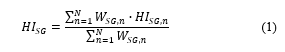
Definition of weights WSG,n should consider limits and recommendations provided by manufacturers and knowledge of experts in the operation and maintenance of MV switchgear. For instance, indicators such as the number of mechanism operations and contact resistance are of great importance for estimating the health status of switchgear [116–118], so they should pose significant weight for computing HISG. However, the health status obtained through those tests (HISG,n) also depends on the intrinsic operating characteristics of the asset, defined by the manufacturer.
b) Remaining life
A methodology for computing the remaining life of MV switchgear based on failure mode analysis and performance analysis of the switchgear’s components using existing data sources is presented in [120]. The approach suggests considering the components and subsystems of MV switchgear and estimating the overall HI as a weighted sum. The specific components and subsystems considered will depend on the type of switchgear, its technology, and its nominal values.
Table 7: Classification of tests on switchgear and diagnostic techniques.
|
|||||||||||||||||||||||||||||||||||||||||||||||||||||||||||||||||||||||||||||||||||||||||||||||||||||||||||||||||||||||||||||||||||||||||||||||||||||||||||||||||||||||||||
6. Overhead lines and underground cables
Lines and cables are highly susceptible to failures due to their long length. Given the great importance of lines and cables in the distribution network, extending their useful life, and making timely decisions to prevent failures and reduce maintenance and operational costs are crucial objectives. Lines and cables maintenance requires considering parameters such as the structural and environmental conditions, useful life, and operating environment. Despite overhead lines and underground cables have the same purpose, i.e., to transport electrical power, in practice, they are very different assets because of constructive aspects. Therefore, they are analyzed separately in the following.
6.1. Overhead lines
A MV overhead line is usually composed by (i) conductors, where the main types are Aluminum Conductor Steel Reinforced (ACSR), All Aluminum Alloy Conductor (AAAC), All Aluminum Conductor (AAC), Aluminum Conductor Composite Core (ACCC) and Aluminum Conductor Steel Supported (ACSS), (ii) porcelain, composite, or glass insulators, (iii) fittings, mainly made of galvanized steel, and including suspension, tension, dead end, splice, and cross-arm fittings, (iv) poles made of wood, concrete, steel or, most recently, composite, i.e., a combination of fiberglass or carbon fiber reinforced polymer materials (PFRV), (v) cross-arms made of immunized wood, galvanized steel or PFRV, with rod or angle iron diagonals, (vi) sectioning and protection equipment including disconnectors, circuit breakers, and fuses, and (vii) guard lightning protection cables, communication cables and grounding systems.
To assess the MV overhead line condition, it is recommended to evaluate their components separately because the variety of materials mentioned above requires different assessment criteria. For instance, failure and aging processes in each material need to be known for each type of component.
6.2. Underground cables
Underground cables are in some cases preferred over overhead lines because of their lower visual impact and higher reliability. However, constructive requirements of underground cables make them more expensive than overhead lines. The main challenges that underground lines must overcome are to provide enough insulation so that the cables can be installed underground, and to dissipate the heat produced during operation.
The commonly used underground cable types are Cross-linked Polyethylene (XLPE), Self-Contained liquid Filled (SCFF), High Pressure, liquid Filled Pipe (HPFF), High pressure, tube Filled with Gas (HPGF), and Solid Cable. Solid cables demand lower maintenance, although monitoring and detecting insulation failures can be challenging. The size of XLPE cables increases with voltage. Typically, each circuit employs three distinct cables, which are enclosed within a buried or side-by-side conduit.
6.3. Methods for diagnosis and condition assessment of lines and cables
Tests and diagnoses are carried out to determine the MV lines and cables health with the objective of prioritizing decision-making in maintenance and to prevent service interruption due to damages. Among the main tests carried out on lines and cables are visual inspection, thermography, ultrasound, conductor analysis, grounding checking, structure verification, etc. [143–146]. Table 8 summarizes and classifies these main tests according to the taxonomy in Figure 3. Furthermore, Table 8 provides information on the corresponding diagnostic techniques, which range from traditional standard guidelines based on expert knowledge to advanced AI-based techniques such as decision trees.
6.4. Indices for condition assessment of lines and cables
Planning of maintenance, renewal or change of MV distribution lines and cables can be determined from asset management, using tools such as the HI calculation. There are some proposals that deal with this issue, for instance, [146] presents a method to compute an HI for overhead lines using visual inspection findings. An example is shown for foundations and poles, knowing that the aging of reinforced concrete is assessed by monitoring the gradual reduction in structural strength over time. Poles are evaluated within a condition range on a scale of 0 to 5, where a rating of 5 indicates a poor technical condition with an operational lifetime in its final stage, and a rating of 0 represents a state of good condition. Within this scale, the presence of longitudinal cracks with widths ranging from 0.3 to 0.6 mm corresponds to a score of 4. A table with the proposed score for different state conditions is detailed in [146].
Finally, the general HI, considering all the components of the overhead line, is computed using the weighted summation in (2).
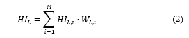
where HIL,i is the index for each line component i, and WL,i its weighting factor, which measures the component importance and is usually defined by utility experts. It is advised to use an exponential scale to convert HIL,i values in (2) to achieve a suitable comparison for extreme values [146].
7. Instrument Transformers (IT)
The signals acquired by IT and subsequently processed and stored by measurement devices, are decisive state variables to control and protect power systems. Two main subsets of IT are Voltage Transformers (VT) and Current Transformers (CT). A VT produces a secondary voltage that is directly proportional to the primary voltage, while a CT generates a secondary current that is proportionate to the primary current. Thereby, VT and CT offer a high-fidelity measurement of voltage and current, respectively, while providing isolation from high voltage and current levels.
On the one hand, there is a variety of VT such as capacitive, resistive-capacitive, and inductive [147]. Inductive VT, for instance, are widely used for measurement and protection in MV networks. On the other hand, there are three types of CT including electromagnetic, capacitive, and optical. Optical CT based on the magneto-optic Faraday effect, are used for measurement and smart grid protection. They have high immunity to electromagnetic disturbances and are suitable for control and protection systems featuring an extensive measurement range. [148].
For any type of IT, reliable measurements are very important. Input signals for protection relays are channeled via IT to execute the protective functions. It is important to highlight that network reliability may be compromised in the event of IT failure, particularly if the input signals for protection and control prove to be imprecise. In this context, it is relevant to identify tests and assessment approaches for IT management.
7.1. Fault diagnosis and condition assessment of IT
The tests to diagnose IT can be carried out with the asset in-service or off-service, as specified by the corresponding standards. These tests allow identifying anomalies or failures and provide some indication of the expected reliability and loss of life of the asset. It should be noted that a single electrical test may not be enough to diagnose the asset, but several tests may be necessary to identify a problem. In addition, the acceptance criteria are specific for each manufacturer.
There are three types of tests including routine tests, carried out on a sample of the equipment, e.g., short circuit withstand tests in CT and VT, and overvoltage test in CT; type tests, applied to one or two identical or similar types of equipment to verify a specific characteristic, e.g., heating test, nominal and safety factor; and maintenance tests, carried out on equipment in-service, to verify its health status after a certain period of operation. A summary of diagnostic tests for IT based on the review is reported in Table 9.
Table 9 also reports diagnostic techniques applied on the results of tests for condition assessment of IT. It is observed that research on condition assessment of IT is still incipient (see also in Table 3 that only 26 records were retrieved with the formulated search rule). Diagnostic techniques found in the literature use, for instance, statistical models such as Weibull, or AI-based techniques including ANN and SVM, as shown in Table 9.
Table 8: Classification of tests on underground cables and overhead lines and diagnostic techniques.
|
|||||||||||||||||||||||||||||||||||||||||||||||||||||||||||||||||||||||||||||||||||||||||||||||||||||||||||||||||||||||||||||||||||||||||||||||||||||||||||||||||||||||||||||||||||||||||||||||||||||||||||||||||
7.2. Indices for condition assessment of IT
Inadequate maintenance practices, environmental factors, and the transformer’s current condition can lead to failures that have an adverse impact on the transformer’s expected lifespan. In this context, the adoption of a predictive approach for asset management and future condition forecasting would allow avoiding failures through early detection of technical problems that may affect the transformer [159]. Research on indices for condition assessment of IT is also very incipient, however, some indicators have been formulated.
a) Loss of life
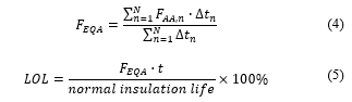
Presently, endeavors are in progress to establish guidelines for estimating the reduction in lifespan of a CT due to short-term overloading. In a related study [160], a thermal accelerated aging method is introduced and implemented on a 69 kV oil-immersed CT subjected to overloading. The laboratory-acquired life test outcomes are validated against analytical assessments involving DP and the analysis of furanic compounds in the transformer oil. The standard IEEE C57.91 is used as a reference to formulate the aging acceleration factor (FAA) as expressed in (3).
![]()
Likewise, the percentage of loss of life (LOL) is calculated resulting from the equivalent acceleration factor (FEQA), the normal life of the insulation (DP = 200) and the duration of the stress (t), according to (4)-(5).
b) Lifetime
Significant thermal aging of paper insulation stands out as a pivotal constraint on the operational lifespan of IT. In [175], research encompasses simulation studies and a comprehensive review of literature pertaining to insulation systems, moisture dynamics, and statistical modeling of IT lifetime data. The primary objective of this research was to identify potential triggers and factors that impact IT failures. Results showed the relationship between failures and age, environmental factors, and operating stress level.
Table 9: Classification of tests on IT and diagnostic techniques.
|
|||||||||||||||||||||||||||||||||||||||||||||||||||||||||||||||||||||||||||||||||||||||||||||||||||||||||||||||||||||||||||||||||||||||||||||||||||||||||||||||||||||||||||||||||||||||||||||||||||||||||||||||||
c) Health Index (HI)
The HI serves as a metric for quantifying the enduring deterioration of a transformer. It combines intricate condition-related information into a singular value, offering a relative assessment of the overall state of a transformer. Most HI methodologies rely on either laboratory or on-site test data, with limited incorporation of actual operational time [159,176].
For instance, the calculation of a CT HI is formulated in [159], where oil tests (furans, acetylene, etc.) are considered, as well as thermal aging factors and other parameters including maintenance, environment, location, failure history, and observed external and internal condition. A life expectancy model of the upgraded CT is developed based on the calculated HI and the HI aging factor. The calculation is given by (6).
![]()
where HIIT-0 is the initial HI considered as 0.05, B is the aging factor, T1 is the year corresponding to HI0 (T1-0 = expected life) and T2 is the year under study (T2-0 = 0).
8. Discussion
A first insight offered by the quantitative review developed in this paper is that only research on condition assessment of PT shows high level of maturity in all the analyzed aspects including tests, diagnostic techniques, and indices. Moreover, condition assessment on PV systems is a topic of increasing interest because of the current relevance of renewable energy resources. Therefore, significant efforts have been put in the topic during the last five years, however, further work should be carried out on indices for condition assessment of PV systems. Regarding condition assessment of DT, switchgear, lines and cables, and IT, research is mature in terms of tests, but still incipient on diagnostic techniques and indices.
Different types of tests, mostly based on widely accepted practices and standards, are applied on the selected MV assets, and a taxonomy was formulated in this paper accordingly. In this sense, according to the operating status of the asset, tests are classified as in-service and off-service. Results of the review summarized in Tables 4-9 demonstrate that a similar amount of in-service, and off-service tests are available for the MV assets dealt within this review. Moreover, according to nature, most of those tests are electrical (as expected because of the electrical nature of the assets), e.g., short-circuit withstand tests, voltage and current measurements, FRA (in PT and DT), followed by physical tests, e.g., visual inspection (in all the analyzed assets), mechanical tests (of particular importance for switchgear), thermography (in all the analyzed assets), and chemical tests (mostly applied to PT and DT), e.g., DP, furan analysis, DGA. No chemical tests were identified in the literature for PV systems, lines, and cables.
Likewise, categories were defined in this review for diagnostic techniques, namely, expert knowledge, analytical models, and AI-based approaches. These diagnostic techniques aim at improving interpretability of test results. From Tables 4-9 and the extensive review, it is seen that most diagnostic techniques are based on expert knowledge (established in standards and widely accepted procedures and industry practice), whereas very few approaches use analytical models probably because of the complex derivation and implementation of physical models that hinders the applicability. However, analytical models are still valuable diagnostic techniques, e.g., in the analysis of PD and corona effect in lines and cables, and the analysis of FRA and acoustic signals in PT and DT.
Furthermore, AI-based diagnostic techniques have been introduced recently to overcome some limitations of conventional methods. For instance, AI models are useful to deal with large volumes of data and to represent complex phenomena with minimal requirement of knowledge and physical interpretation (black-box approaches). Examples of AI-based diagnostic techniques are ANN for multiple applications such as interpretation of FRA and DFR in PT and DT, model parameters identification in PV systems, and PD and acoustic analysis in switchgear, lines, and cables. Other AI-based diagnostic techniques have been applied including decision trees, SVM, fuzzy logic, optimization methods, expert systems, kNN, and, to a lesser extent, deep learning models such as CNN, DBF, and LSTM.
9. Prospects for future research
The results of the review demonstrate that research on condition monitoring of some critical MV assets is incipient, especially regarding indices for asset management. Therefore, the need for further research in this topic is highlighted. For instance, HI for PV systems, DT, switchgear, lines, cables, and IT, should be further investigated to obtain a proper health characterization of each asset and its subsystems according to the application, e.g., investment decision-making, network planning, and maintenance scheduling. In this context, straightforward computation of HI based on weighted sums should be explored given its applicability to real-world scenarios, and extensive study cases should be analyzed to demonstrate the benefits of condition monitoring of MV assets for cost-effective operation of distribution networks.
Root cause failure analysis, forecasting of health status, and incipient fault detection based on condition monitoring are also promising areas of research. Applications of these research lines include failure mitigation measures, and predictive maintenance to improve useful life of the assets. Several techniques have demonstrated satisfactory results and capabilities in this direction. For instance, root cause analysis using supervised AI tools such as ANN, SVM, and decision trees has been performed. However, these approaches need large volumes of labelled training data and suffer from overfitting. Moreover, Markov chains have been used for health status forecasting and informed decision-making in asset management. Nonetheless, forecasting capabilities of Markov chains are limited because of the lack of long-term dependencies or representation of trends on data. Other promising approaches for health status forecasting and incipient fault detection include supervised and unsupervised deep learning techniques such as LSTM and deep autoencoders. In this case, drawbacks are on the requirement of large datasets for training and the limited interpretability of models.
As mentioned above, the use of AI techniques for advanced applications in condition monitoring require large datasets. In this regard, new technologies are increasingly adopted by network operators for widespread acquisition of offline and real-time data, e.g., IoT, and advanced metering infrastructures. To properly exploit this huge amount of data, big data frameworks and cloud-based applications with high performance capabilities should be studied in detail, and potentialities should be envisaged.
Finally, lack of integrated tools for asset management and condition monitoring considering most critical assets of the MV network, e.g., PT, PV systems, DT, switchgear, lines, cables, and IT, is observed. Consequently, the analysis, implementation, and research on case studies with the application of comprehensive asset management and condition monitoring methodologies on distribution networks considering all the critical assets is highly encouraged to take advantage of current technology infrastructures and high availability of data to improve the efficient operation of modern power networks. In this context, the use of optimization methods for the integrated operation of distribution networks based on asset management and condition monitoring is seen as a prolific prospective area of research.
10. Conclusion
This paper extends the work presented in ARGENCON 2022 [1]. This extended review examines the literature on critical MV assets operating in distribution networks, namely, PT, PV systems, DT, switchgear, lines and cables, and IT. Moreover, this work is developed in the context of a government-funded research project in Colombia aimed at implementing a digital platform for asset management of distribution network components at the archipelago of San Andrés, Providencia, and Santa Catalina. In this context, the review offers a detailed study of the main technical aspects of each asset and its subsystems, as well as the main parameters for condition assessment. The contributions of this paper are summarized as follows:
- A systematic methodology is adopted for the review and bibliographic data retrieval, where advanced search rules are formulated, and the obtained academic publications are complemented with diverse literature including standards, reports, and relevant white papers.
- A quantitative analysis of the status of research on condition assessment of MV assets is provided, highlighting maturity on the study of PT, the increasing interest in PV systems, and the lack of research on DT, switchgear, lines and cables, and IT.
- A taxonomy for tests and diagnostic techniques used for condition monitoring of MV assets is defined and the extensive literature is classified accordingly (see Tables 4-9).
- Based on the classification above, the main technical aspects related to methods for diagnosis and condition assessment of each asset and indices related to condition assessment are developed.
Regarding the main findings and research gaps, the review identifies the types of tests and diagnostic techniques applied to MV assets, with electrical tests being the most common. Analytical models and AI-based approaches show promise in improving the capability to analyze test results. The prospects for future research lie in developing comprehensive HI for various MV assets, root cause failure analysis, forecasting health status, and incipient fault detection using advanced AI techniques such as deep learning. Leveraging big data and cloud-based applications are suggested to exploit the growing amount of data from emerging technologies, and the integration of condition monitoring and asset management methodologies is crucial for enhancing the efficient operation of modern power distribution networks.
List of symbols
B Aging factor
FAA Aging acceleration factor
FEQA Equivalent acceleration factor
HIIT Health index of IT
HIIT-0 Initial health index of IT
HIL Health index of line
HIL,i Health index of line component i
HISG Health index of switchgear
HISG,n Health index obtained in test n on switchgear
LOL Percentage of loss of life
t Duration of stress
T1 Year corresponding to HI0
T1-0 Expected life
T2 Year under study
WL,i Weighting factor of line component i
WSG,n Weight for test n on switchgear
qH Hot Spot Temperature
Conflict of Interest
The authors declare no conflict of interest.
Acknowledgment
Financial support by Fondo de Ciencia, Tecnología e Innovación (FCTeI) of Sistema General de Regalías (SGR) under project BPIN 2021000100223 entitled “Implementation of a digital platform to increase the use of the electrical network assets of the Archipelago of San Andrés and Providencia” is greatly acknowledged.
- C. Madrid-Chirinos, A.A. Romero-Quete, L. Ontiveros, A. Sarasua, “Condition Assessment of High Voltage Instrument Transformers: A Bibliometric Analysis and Literature Review,” in 2022 IEEE Biennial Congress of Argentina (ARGENCON), IEEE: 1–8, 2022, doi:10.1109/ARGENCON55245.2022.9939980.
- ISO-55000, Asset Management – Overview, principles and terminology, Switzerland, 2014.
- D. Moher, A. Liberati, J. Tetzlaff, D.G. Altman, D. Altman, G. Antes, D. Atkins, V. Barbour, N. Barrowman, J.A. Berlin, J. Clark, M. Clarke, D. Cook, R. D’Amico, J.J. Deeks, P.J. Devereaux, K. Dickersin, M. Egger, E. Ernst, P.C. Gøtzsche, J. Grimshaw, G. Guyatt, J. Higgins, J.P.A. Ioannidis, J. Kleijnen, T. Lang, N. Magrini, D. McNamee, L. Moja, et al., Preferred reporting items for systematic reviews and meta-analyses: The PRISMA statement, PLoS Medicine, 2009, doi:10.1371/journal.pmed.1000097.
- R.D. Stebbins, D.S. Myers, A.B. Shkolnik, “Furanic compounds in dielectric liquid samples: Review and update of diagnostic interpretation and estimation of insulation ageing,” in Proceedings of the IEEE International Conference on Properties and Applications of Dielectric Materials, 921–926, 2003.
- H. de Faria, J.G.S. Costa, J.L.M. Olivas, “A review of monitoring methods for predictive maintenance of electric power transformers based on dissolved gas analysis,” Renewable and Sustainable Energy Reviews, 46, 201–209, 2015, doi:10.1016/j.rser.2015.02.052.
- C. AJ, M.A. Salam, Q.M. Rahman, F. Wen, S.P. Ang, W. Voon, “Causes of transformer failures and diagnostic methods – A review,” Renewable and Sustainable Energy Reviews, 82, 1442–1456, 2018, doi:10.1016/j.rser.2017.05.165.
- R. Soni, B. Mehta, “Review on asset management of power transformer by diagnosing incipient faults and faults identification using various testing methodologies,” Engineering Failure Analysis, 128, 105634, 2021, doi:10.1016/j.engfailanal.2021.105634.
- A.R. Abbasi, “Fault detection and diagnosis in power transformers: a comprehensive review and classification of publications and methods,” Electric Power Systems Research, 209, 107990, 2022, doi:10.1016/j.epsr.2022.107990.
- L. Jin, D. Kim, A. Abu-Siada, S. Kumar, “Oil-Immersed Power Transformer Condition Monitoring Methodologies: A Review,” Energies, 15(9), 3379, 2022, doi:10.3390/en15093379.
- A. Azmi, J. Jasni, N. Azis, M.Z.A.A. Kadir, “Evolution of transformer health index in the form of mathematical equation,” Renewable and Sustainable Energy Reviews, 76, 687–700, 2017, doi:10.1016/j.rser.2017.03.094.
- IEEE Std 62-1995, IEEE Guide for Diagnostic Field Testing of Electric Power Apparatus – Part 1: Oil Filled Power Transformers, Regulators, and Reactors, 1–64, 1995.
- IEC-60450:2004, Measurement of the Average Viscometric Degree of Polymerization of New and Aged Cellulosic Electrically Insulating Materials, 1–45, 2004.
- IEEE PC57.149/D9.2, IEEE Draft Guide for the Application and Interpretation of Frequency Response Analysis for Oil Immersed Transformers, 1–68, 2012.
- IEEE Std C57.152-2013, IEEE Guide for Diagnostic Field Testing of Fluid-Filled Power Transformers, Regulators, and Reactors, 1–121, 2013.
- IEEE PC57.104/D6.2, IEEE Approved Draft Guide for the Interpretation of Gases Generated in Oil-Immersed Transformers, 1–103, 2019.
- S. Birlasekaran, F. Fetherston, “Off/on-line FRA condition monitoring technique for power transformer,” IEEE Power Engineering Review, 19(8), 54–56, 1999, doi:10.1109/39.780991.
- B. Noirhomme, E. David, H. Garbi, M.C. Lessard, R. Boissonneault, “Application of dielectric response techniques for the condition assessment of power transformers,” in CEIDP ’05. 2005 Annual Report Conference on Electrical Insulation and Dielectric Phenomena, 2005., IEEE: 273–276, 2005, doi:10.1109/CEIDP.2005.1560674.
- F.A. Wegelin, R.S. Magalhães, L.A.L. De Almeida, M. Fontana, “Condition monitoring of power transformers using acoustic signal Prony’s analysis,” in Conference Record – IEEE Instrumentation and Measurement Technology Conference, 1384–1387, 2005, doi:10.1109/IMTC.2004.1351324.
- D. Duval, “Dissolved Gas Analysis and the Duval Triangle,” 1–20, 2006.
- Z. Abdul-Malek, N. Bashir, H. Ismail, “Furan analysis on power transformers in Malaysia: A field investigation,” International Review on Modelling and Simulations, 4(5), 2227–2233, 2011.
- G. Csépes, B. Németh, Cs. Vörös, “Practicable expert system for the improved interpretation of dielectric response diagnostic methods of power transformers,” in 44th International Conference on Large High Voltage Electric Systems 2012, 2012.
- M.J. Liu, J.Z. Zou, Q.K. Zhou, Y.L. Li, N.P. Yan, “On-Line Condition Monitoring for Power Transformers Based on UHF PD Measurements,” Advanced Materials Research, 614–615, 1158–1162, 2012, doi:10.4028/www.scientific.net/AMR.614-615.1158.
- S. Tenbohlen, M. Heindl, M. Jovalekic, “On-site PD Diagnostics, FRA and Moisture Measurement for Power Transformers,” IEEJ Transactions on Power and Energy, 132(2), 134–138, 2012, doi:10.1541/ieejpes.132.134.
- H. Gago Garcia, F. Garnacho Vecino, M.A. Sánchez-Uran, J. Ortego La Moneda, I. Uliarte Ranea, “Condition assessment of power transformers in service using pd monitoring,” in CIGRE Session 46, 2016.
- A.A. Romero-Quete, E.E. Mombello, G. Rattá, “Assessing the loss-of-insulation life of power transformers by estimating their historical loads and ambient temperature profiles using ANNs and Monte Carlo simulations,” DYNA (Colombia), 83(197), 104–113, 2016, doi:10.15446/dyna.v83n197.48134.
- A. Hekmati, R. Hekmati, “Optimum acoustic sensor placement for partial discharge allocation in transformers,” IET Science, Measurement & Technology, 11(5), 581–589, 2017, doi:10.1049/iet-smt.2016.0417.
- J. Liu, H. Zheng, Y. Zhang, H. Wei, R. Liao, “Grey Relational Analysis for Insulation Condition Assessment of Power Transformers Based Upon Conventional Dielectric Response Measurement,” Energies, 10(10), 1526, 2017, doi:10.3390/en10101526.
- R.D. Medina, A.A. Romero, E.E. Mombello, G. Rattá, “Assessing degradation of power transformer solid insulation considering thermal stress and moisture variation,” Electric Power Systems Research, 151, 1–11, 2017, doi:10.1016/j.epsr.2017.04.006.
- N. Roopnarine, A. Singh, C.J. Ramlal, S. Rocke, “Network Synthesis of Transformer Winding for FRA Interpretation,” in 2016 8th International Conference on Computational Intelligence and Communication Networks (CICN), IEEE: 493–497, 2016, doi:10.1109/CICN.2016.102.
- N. Yao, X. Wu, “Transformer fault detection based on infrared power image,” Acta Technica CSAV (Ceskoslovensk Akademie Ved), 62(2), 237–243, 2017.
- S. Seifi, A. Akbari, P. Werle, H. Mohseni, A.A.S. Akmal, “A sensitivity analysis of RLC transformer winding model parameters used for a PD localization,” in 2018 IEEE 2nd International Conference on Dielectrics (ICD), IEEE: 1–4, 2018, doi:10.1109/ICD.2018.8468521.
- M. Koch, M. Anglhuber, “Experiences with Measurement and Analysis of the Dielectric Response of Instrument Transformers,” in 2018 IEEE International Conference on High Voltage Engineering and Application (ICHVE), IEEE: 1–4, 2018, doi:10.1109/ICHVE.2018.8642206.
- E.T. Mharakurwa, R. Goboza, “Multiparameter-Based Fuzzy Logic Health Index Assessment for Oil-Immersed Power Transformers,” Advances in Fuzzy Systems, 2019, 1–12, 2019, doi:10.1155/2019/2647157.
- Y.O. Shaker, “Detection of partial discharge acoustic emission in power transformer,” International Journal of Electrical and Computer Engineering (IJECE), 9(6), 4573, 2019, doi:10.11591/ijece.v9i6.pp4573-4579.
- A.F. Cerón, R.A. Lozano, G. Aponte, A.A. Romero, “Hot spot temperature estimation in mineral oil immersed power transformers using support vectors regression,” Informacion Tecnologica, 31(4), 35–44, 2020, doi:10.4067/S0718-07642020000400035.
- R. Cselkó, M. Szirtes, G. Csépes, Speciality and Applicability of Advanced Response Methods in Contrast to the Traditional Dielectric Measurements for Condition Assessment of Power Transformers, 1003–1014, 2020, doi:10.1007/978-3-030-31676-1_94.
- S.J.T. Shahrabad, V. Ghods, M.T. Askari, “Power transformer fault diagnosis using DGA and artificial intelligence,” Recent Advances in Computer Science and Communications, 13(4), 579–587, 2020, doi:10.2174/2213275912666190212124133.
- H.C. Chen, Y. Zhang, M. Chen, “Online DGA Sensor Calibration Using GANN and Data Augmentation,” in Proceedings of 2022 IEEE 5th International Electrical and Energy Conference, CIEEC 2022, 1426–1430, 2022, doi:10.1109/CIEEC54735.2022.9846119.
- R. Emadifar, N.T. Kalantari, V. Behjat, R. Najjar, “Monitoring and Condition Assessment of Insulation Paper of Distribution Transformers With Novel Oil Spectroscopy Method,” IEEE Transactions on Dielectrics and Electrical Insulation, 29(5), 1904–1912, 2022, doi:10.1109/TDEI.2022.3199687.
- X. Ma, Y. Luo, J. Shi, H. Xiong, “Acoustic Emission Based Fault Detection of Substation Power Transformer,” Applied Sciences, 12(5), 2759, 2022, doi:10.3390/app12052759.
- M. Zulkifli, M.Z. Muthaza, I. Safaat, S.S. Yi, N. Sahari, “Thermography Study on Distribution Transformer in Substation: Transformer Core Material,” International Journal of Engineering Trends and Technology, 71(3), 9–16, 2022, doi:10.14445/22315381/IJETT-V71I3P202.
- A. Naderian, S. Cress, R. Piercy, F. Wang, J. Service, “An Approach to Determine the Health Index of Power Transformers,” in Conference Record of the 2008 IEEE International Symposium on Electrical Insulation, IEEE: 192–196, 2008, doi:10.1109/ELINSL.2008.4570308.
- M. Arshad, S. Islam, A. Khaliq, “Fuzzy logic approach in power transformers management and decision making,” IEEE Transactions on Dielectrics and Electrical Insulation, 21(5), 2343–2354, 2014, doi:10.1109/TDEI.2014.003859.
- A.F. Cerón, D.F. Echeverry, G. Aponte, A.A. Romero, “Health index for power transformers immersed in mineral oil with voltages between 69kV and 230kV using fuzzy logic,” Informacion Tecnologica, 26(2), 107–116, 2015, doi:10.4067/S0718-07642015000200013.
- Juan.P. Lata, Diego.P. Chacon-Troya, R.D. Medina, “Improved tool for power transformer health index analysis,” in 2017 IEEE XXIV International Conference on Electronics, Electrical Engineering and Computing (INTERCON), IEEE: 1–4, 2017, doi:10.1109/INTERCON.2017.8079656.
- C. Ranga, A.K. Chandel, “Expert System for Health Index Assessment of Power Transformers,” International Journal on Electrical Engineering and Informatics, 9(4), 850–865, 2017, doi:10.15676/ijeei.2017.9.4.16.
- A.M. Abdullah, R. Ali, S.B. Yaacob, K. Ananda-Rao, N.A. Uloom, “Transformer Health Index by Prediction Artificial Neural Networks Diagnostic Techniques,” Journal of Physics: Conference Series, 2312(1), 012002, 2022, doi:10.1088/1742-6596/2312/1/012002.
- D. Luo, R. Xi, L. Che, H. He, “Health condition assessment of transformers based on cross message passing graph neural networks,” Frontiers in Energy Research, 10, 2022, doi:10.3389/fenrg.2022.973736.
- K. Ramalingam, C. Indulkar, Solar Energy and Photovoltaic Technology, 2017, doi:10.1016/B978-0-12-804208-3.00003-0.
- International Energy Agency, Trends in photovoltaic applications 2022 – Report IEA PVPS T1-43:2022, 2022.
- L. Hernández-Callejo, S. Gallardo-Saavedra, V. Alonso-Gómez, “A review of photovoltaic systems: Design, operation and maintenance,” Solar Energy, 188, 426–440, 2019, doi:10.1016/j.solener.2019.06.017.
- S. Lu, B.T. Phung, D. Zhang, “A comprehensive review on DC arc faults and their diagnosis methods in photovoltaic systems,” Renewable and Sustainable Energy Reviews, 89, 88–98, 2018, doi:10.1016/j.rser.2018.03.010.
- A. Mellit, G.M. Tina, S.A. Kalogirou, “Fault detection and diagnosis methods for photovoltaic systems: A review,” Renewable and Sustainable Energy Reviews, 91, 1–17, 2018, doi:10.1016/j.rser.2018.03.062.
- D.S. Pillai, N. Rajasekar, “A comprehensive review on protection challenges and fault diagnosis in PV systems,” Renewable and Sustainable Energy Reviews, 91, 18–40, 2018, doi:10.1016/j.rser.2018.03.082.
- D.S. Pillai, N. Rajasekar, “Metaheuristic algorithms for PV parameter identification: A comprehensive review with an application to threshold setting for fault detection in PV systems,” Renewable and Sustainable Energy Reviews, 82, 3503–3525, 2018, doi:10.1016/j.rser.2017.10.107.
- Syafaruddin, D.S. Zinger, “Review on methods of fault diagnosis in photovoltaic system applications,” Journal of Engineering Science and Technology Review, 12(5), 53–66, 2019, doi:10.25103/jestr.125.07.
- L.B. Bosman, W.D. Leon-Salas, W. Hutzel, E.A. Soto, “PV system predictive maintenance: Challenges, current approaches, and opportunities,” Energies, 16(3), 2020, doi:10.3390/en13061398.
- A. Kumaradurai, Y. Teekaraman, T. Coosemans, M. Messagie, “Fault detection in photovoltaic systems using machine learning algorithms: A review,” Institute of Electrical and Electronics Engineers Inc., Automotive Technology Research Group (MOBI), Vrije Universiteit Brussel (VUB), Brussels, Belgium, 2020, doi:10.1109/ICOT51877.2020.9468768.
- T. Berghout, M. Benbouzid, T. Bentrcia, X. Ma, S. Djurović, L.-H. Mouss, “Machine learning-based condition monitoring for pv systems: State of the art and future prospects,” Energies, 14(19), 2021, doi:10.3390/en14196316.
- T. Berghout, M. Benbouzid, X. Ma, S. Djurovic, L.-H. Mouss, “Machine Learning for Photovoltaic Systems Condition Monitoring: A Review,” IEEE Computer Society, University of Batna2, Department of Industrial Engineering and Manufacturing, Batna, Algeria, 2021, doi:10.1109/IECON48115.2021.9589423.
- C. Feng, Y. Liu, J. Zhang, “A taxonomical review on recent artificial intelligence applications to PV integration into power grids,” International Journal of Electrical Power and Energy Systems, 132, 2021, doi:10.1016/j.ijepes.2021.107176.
- A.W. Kandeal, M.R. Elkadeem, A. Kumar Thakur, G.B. Abdelaziz, R. Sathyamurthy, A.E. Kabeel, N. Yang, S.W. Sharshir, “Infrared thermography-based condition monitoring of solar photovoltaic systems: A mini review of recent advances,” Solar Energy, 223, 33–43, 2021, doi:10.1016/j.solener.2021.05.032.
- M. Mansouri, M. Trabelsi, H. Nounou, M. Nounou, “Deep Learning-Based Fault Diagnosis of Photovoltaic Systems: A Comprehensive Review and Enhancement Prospects,” IEEE Access, 9, 126286–126306, 2021, doi:10.1109/ACCESS.2021.3110947.
- A.K. V de Oliveira, M. Aghaei, R. Rüther, “Automatic Inspection of Photovoltaic Power Plants Using Aerial Infrared Thermography: A Review,” Energies, 15(6), 2022, doi:10.3390/en15062055.
- M.I.S. Guerra, F.M.U. de Araújo, J.T. de Carvalho Neto, R.G. Vieira, “Survey on adaptative neural fuzzy inference system (ANFIS) architecture applied to photovoltaic systems,” Energy Systems, 2022, doi:10.1007/s12667-022-00513-8.
- Z. Yuan, G. Xiong, X. Fu, “Artificial Neural Network for Fault Diagnosis of Solar Photovoltaic Systems: A Survey,” Energies, 15(22), 8693, 2022, doi:10.3390/en15228693.
- D.C. Jordan, S.R. Kurtz, “Photovoltaic Degradation Rates-an Analytical Review,” Progress in Photovoltaics: Research and Applications, 21(1), 12–29, 2013, doi:10.1002/pip.1182.
- O.A. Alimi, E.L. Meyer, O.I. Olayiwola, “Solar Photovoltaic Modules’ Performance Reliability and Degradation Analysis—A Review,” Energies, 15(16), 5964, 2022, doi:10.3390/en15165964.
- IEC 62446-1:2016, Photovoltaic (PV) systems – Requirements for testing, documentation and maintenance – Part 1: Grid connected systems – Documentation, commissioning tests and inspection, 1–83, 2016.
- IEEE Std 1547-2018, IEEE Standard for Interconnection and Interoperability of Distributed Energy Resources with Associated Electric Power Systems Interfaces, 1–138, 2018.
- IEEE Std 1526-2020, IEEE Recommended Practice for Testing the Performance of Stand-Alone Photovoltaic Systems, 1–32, 2020.
- I. Bodnár, D. Matusz-Kalász, R.R. Boros, R. Lipták, “Condition Assessment of Solar Modules by Flash Test and Electroluminescence Test,” Coatings, 11(11), 1361, 2021, doi:10.3390/coatings11111361.
- V. Esen, S. Saglam, B. Oral, O. Ceylan Esen, “Toward Class AAA LED Large Scale Solar Simulator With Active Cooling System for PV Module Tests,” IEEE Journal of Photovoltaics, 12(1), 364–371, 2022, doi:10.1109/JPHOTOV.2021.3117912.
- S. Choi, S. Park, J. Hong, J. Won, “A Design and Validation of 400 W PV Emulator Using Simple Equivalent Circuit for PV Power System Test,” Energies, 16(4), 1561, 2023, doi:10.3390/en16041561.
- C. Han, H. Lee, “A field-applicable health monitoring method for photovoltaic system,” Reliability Engineering & System Safety, 184, 219–227, 2019, doi:10.1016/j.ress.2018.01.002.
- P. Ramanan, K. Kalidasa Murugavel, A. Karthick, “Performance analysis and energy metrics of grid-connected photovoltaic systems,” Energy for Sustainable Development, 52, 104–115, 2019, doi:10.1016/j.esd.2019.08.001.
- SolarPower Europe, Asset management best practice guidelines Version 2.0, 2020.
- IEC, IEC 60076-7. Power transformers – Loading guide for mineral-oil-immersed power transformers, Genova, Switzerland, 2018.
- IEC, IEC 60076-7. Power transformers – Loading guide for oil-immersed power transformers., Genova, Switzerland, 2005.
- F. Kabir, B. Foggo, N. Yu, “Data driven predictive maintenance of distribution transformers,” IEEE Computer Society, Department of Electrical and Engineering, University of California, Riverside, CA 92507, United States: 312–316, 2018, doi:10.1109/CICED.2018.8592417.
- G.C. Jaiswal, M.S. Ballal, P.A. Venikar, D.R. Tutakne, H.M. Suryawanshi, “Genetic algorithm–based health index determination of distribution transformer,” International Transactions on Electrical Energy Systems, 28(5), 2018, doi:10.1002/etep.2529.
- IEEE, IEEE Std C57.12.00-2010 – Standard for General Requirements for Liquid-Immersed Distribution, Power, and Regulating Transformers, New York, United State, 2010.
- K. Azimi Hosseini, M. Hajiaghapour-Moghimi, E. Hajipour, M. Vakilian, “Advanced distribution transformer asset management embracing its relocation: A cost saving approach,” IET Generation, Transmission and Distribution, 16(12), 2370–2385, 2022, doi:10.1049/gtd2.12456.
- Meghalaya State Electricity Board, Manual for Maintenance of Distribution Transformers, 2010.
- M.M. Youssef, R.A. Ibrahim, H. Desouki, M.M.Z. Moustafa, “An Overview on Condition Monitoring & Health Assessment Techniques for Distribution Transformers,” Institute of Electrical and Electronics Engineers Inc., Arab Academy for Science, Technology & Maritime Transport, Alexandria, Egypt: 187–192, 2022, doi:10.1109/ICGEA54406.2022.9791900.
- IEEE, IEEE Std 62-1995 – Guide for Diagnostic Field Testing of Electric Power Apparatus – Part 1: Oil Filled Power Transformers, Regulators, and Reactors., 1995.
- R. Behkam, H. Karami, M.S. Naderi, G.B. Gharehpetian, “Condition Monitoring of Distribution Transformers Using Frequency Response Traces and Artificial Neural Network to Detect the Extent of Windings Axial Displacements,” Institute of Electrical and Electronics Engineers Inc., Amirkabir University of Technology (Tehran Polytechnic), Department of Electrical Engineering, Iran: 18–23, 2022, doi:10.1109/EPDC56235.2022.9817296.
- A. Sbravati, R. Breazeal, D. Robalino, “Practical Considerations for the Usage of Ester Fluids in Distribution Transformers,” Institute of Electrical and Electronics Engineers Inc., Cargill Bioindustrial, Minneapolis, United States: 366–371, 2022, doi:10.1109/EIC51169.2022.9833213.
- R. Chumnuan, D. Rerkpreedapong, “A practicable framework for risk assessment of distribution transformers using PEA smart meter data,” in: Y., K., ed., Institute of Electrical and Electronics Engineers Inc., Provincial Electricity Authority (PEA), Engineering Division Region 4, Bangkok, Thailand: 590–594, 2021, doi:10.1109/ECTI-CON51831.2021.9454682.
- R. Prananda, H.S. Dini, T.W.O. Putri, “Design of Load Balancing Method on Secondary Distribution Network Using Artificial Intelligence Based on Fuzzy Logic,” Institute of Electrical and Electronics Engineers Inc., Institut Teknologi PLN, Faculty of Electricity and Renewable Energy, Jakarta, Indonesia: 372–377, 2021, doi:10.1109/ICHVEPS53178.2021.9600977.
- C.-S. Tu, C.-Y. Yang, M.-T. Tsai, “An optimal phase arrangement of distribution transformers under risk assessment,” Energies, 13(21), 2020, doi:10.3390/en13215852.
- Z. Yang, Y. Shen, R. Zhou, F. Yang, Z. Wan, Z. Zhou, “A transfer learning fault diagnosis model of distribution transformer considering multi-factor situation evolution,” IEEJ Transactions on Electrical and Electronic Engineering, 15(1), 30–39, 2020, doi:10.1002/tee.23024.
- S. Kulkarni, K. Ashok, F. Lambert, D. Divan, “Asset Monitoring using Smart Sensing and Advanced Analytics for the Distribution Network,” Institute of Electrical and Electronics Engineers Inc., Center for Distributed Energy, Georgia Institute of Technology, Atlanta, GA, United States, 2019, doi:10.1109/NAPS46351.2019.9000254.
- G.C. Jaiswal, M.S. Ballal, D.R. Tutakne, P. Vishnu, “Intelligent condition monitoring system for distribution transformer and health status diagnosis,” Institute of Electrical and Electronics Engineers Inc., Additional Executive Engineer, Maharashtra State Elec. Distr. Co. Ltd. and Res. Scholar Shri Ramdeobaba Coll. of Eng. and Mgmt., Nagpur, India: 1–6, 2018, doi:10.1109/PICC.2018.8384786.
- M. Mahoor, A. Majzoobi, A. Khodaei, “Distribution asset management through coordinated microgrid scheduling,” IET Smart Grid, 1(4), 159–168, 2018, doi:10.1049/iet-stg.2018.0076.
- A.A. Nelson, G.C. Jaiswal, M.S. Ballal, D.R. Tutakne, “Remote condition monitoring system for distribution transformer,” Institute of Electrical and Electronics Engineers Inc., Dept of Elect Engg, VNIT, Nagpur, India, 2015, doi:10.1109/NPSC.2014.7103848.
- Y.B. Chen, Y. Sun, X.R. Sun, G.H. Sheng, X.C. Jiang, Real-time temperature on-line monitoring and analysis system for transformers, 521, 409–413, 2014, doi:10.4028/www.scientific.net/AMM.521.409.
- B. Noirhomme, J. Jalbert, M.-C. Lessard, F. Brochu, S. Hachichi, “Pole mounted distribution transformers insulation condition assessment,” Hydro-Québec – IREQ, Varennes, Canada: 239–243, 2013, doi:10.1109/EIC.2013.6554241.
- S. Carvalhosa, H. Leite, F. Branco, C.A. Sá, A.M. Moura, R.C. Lopes, M. Soares, “Survey on the Advancements of Dielectric Fluids and Experiment Studies for Distribution Power Transformers,” Renewable Energy and Power Quality Journal, 19, 97–102, 2021, doi:10.24084/repqj19.225.
- Y. Wang, L. Hu, J. Chen, Y. Ren, “Health status diagnosis of distribution transformers based on big data mining,” Transactions on Emerging Telecommunications Technologies, 33(2), 2022, doi:10.1002/ett.3759.
- N.S. Shariffuddin, N. Azis, A.M. Selva, M.S. Yahaya, J. Jasni, M.A. Talib, “Investigation on the Relationship between Failure Rates and Health Index of Distribution Transformer Population,” Institute of Electrical and Electronics Engineers Inc., Universiti Putra Malaysia, Advanced Lightning, Power and Energy Research Centre (ALPER), Serdang, Malaysia: 119–122, 2021, doi:10.1109/ICPADM49635.2021.9493977.
- S.A. Ghani, Y.H.M. Thayoob, Y.Z.Y. Ghazali, M.S.A. Khiar, I.S. Chairul, “Condition monitoring of distribution transformer’s mechanical parts using sweep frequency response analysis (SFRA),” Elsevier Ltd, Universiti Teknikal Malaysia Melaka, Hang Tuah Jaya, 76100 Durian Tunggal, Melaka, Malaysia: 469–476, 2013, doi:10.1016/j.proeng.2013.12.208.
- S. Zhu, C.J. Kikkert, N. Ertugrul, “A wide bandwidth, on-line impedance measurement method for power systems, based On PLC techniques,” in 2014 IEEE International Symposium on Circuits and Systems (ISCAS), IEEE, School of Electrical and Electronic Engineering, University of Adelaide, Adelaide, SA, Australia: 1167–1170, 2014, doi:10.1109/ISCAS.2014.6865348.
- J. Javid, M.A. Mughal, M. Karim, “Using kNN Algorithm for classification of Distribution transformers Health index,” Institute of Electrical and Electronics Engineers Inc., HITEC University Taxila, Department of Electrical Engineering, Taxila, Pakistan, 2021, doi:10.1109/ICIC53490.2021.9693013.
- R.R. Pawar, S.B. Deosarkar, “Health condition monitoring system for distribution transformer using Internet of Things (IoT),” Institute of Electrical and Electronics Engineers Inc., Department of Electronics and Telecommunication Engineering, Dr. Babasaheb Ambedkar Technological University, Lonere, Raigad, Maharashtra, India: 117–122, 2018, doi:10.1109/ICCMC.2017.8282650.
- P. Henault, “Detection of internal arcing faults in distribution transformers,” IFD Corporation, United States, 2011, doi:10.1109/TDCLLM.2011.6042220.
- L. Bin, S. Sheng, L. Yuan, F. Qiang, X. Yunfeng, L. Guanke, “Spectro-Temporal Self-similarity based Identification of Corrupted Acoustic Signal of Distribution Transformer in Noisy Environment,” IEEE Transactions on Power Delivery, 1–12, 2022, doi:10.1109/TPWRD.2022.3181978.
- IEC, IEC 60270 – High-voltage test techniques-Partial discharge measurements., 2001.
- Network Operators in Great Britain, DNO COMMON NETWORK ASSET INDICES METHODOLOGY Health & Criticality-Version 2.1, 2021.
- G.C. Jaiswal, M.S. Ballal, D.R. Tutakne, “Health index based condition monitoring of distribution transformer,” Institute of Electrical and Electronics Engineers Inc., Department of Electrical Engineering, Shri Ramdeobaba College of Engineering & Management, Nagpur, India: 1–5, 2017, doi:10.1109/PEDES.2016.7914222.
- G.C. Montanari, R. Ghosh, L. Cirioni, G. Galvagno, S. Mastroeni, “Partial Discharge Monitoring of Medium Voltage Switchgears: Self-Condition Assessment Using an Embedded Bushing Sensor,” IEEE Transactions on Power Delivery, 37(1), 85–92, 2022, doi:10.1109/TPWRD.2021.3053658.
- I.A. Metwally, “Technology progress in high-voltage gas-insulated substations,” IEEE Potentials, 29(6), 25–32, 2010, doi:10.1109/MPOT.2010.939085.
- X. Zhang, E. Gockenbach, “Component reliability modeling of distribution systems based on the evaluation of failure statistics,” IEEE Transactions on Dielectrics and Electrical Insulation, 14(5), 1183–1191, 2007, doi:10.1109/TDEI.2007.4339478.
- X. Zhang, E. Gockenbach, V. Wasserberg, H. Borsi, “Estimation of the lifetime of the electrical components in distribution networks,” IEEE Transactions on Power Delivery, 22(1), 515–522, 2007, doi:10.1109/TPWRD.2006.876661.
- K. Niayesh, M. Runde, Power Switching Components, Springer International Publishing, Cham, 2017, doi:10.1007/978-3-319-51460-4.
- Power and Water Corporation, “Asset Management Plan – Distribution Switchgear,” 1–54, 2019.
- C. Lowsley, N. Davies, D. Miller, “EFFECTIVE CONDITION ASSESSMENT OF MV SWITCHGEAR,” in ea technology, 1–8.
- Cigré, Non-intrusive methods for condition assessment of distribution and transmission switchgear, Cigré, 2018.
- Y. Alsumaidaee, C. Yaw, S. Koh, S. Tiong, C. Chen, K. Ali, “Review of Medium-Voltage Switchgear Fault Detection in a Condition-Based Monitoring System by Using Deep Learning,” Energies, 15(18), 6762, 2022, doi:10.3390/en15186762.
- K. Perdon, L. Cavalli, M. Testa, “INNOVATIVE ANALYTICS TO ESTIMATE THE PROBABILITY OF FAILURE AND REMAINING USEFUL LIFE OF MEDIUM VOLTAGE BREAKERS,” in Cired 2017, 12–15, 2017.
- A.A. Bhole, W.Z. Gandhare, “An Overview of Dynamic Contact Resistance Measurement of HV Circuit Breakers,” Journal of The Institution of Engineers (India): Series B, 97(2), 219–226, 2016, doi:10.1007/s40031-014-0164-2.
- IEC, IEC 62271-1:2017/AMD1:2021 Amendment 1 – High-voltage switchgear and controlgear – Part 1: Common specifications for alternating current switchgear and controlgear, 2021.
- X. Jiang, B. Stephen, T. Chandarasupsang, S.D.J. McArthur, B.G. Stewart, “A Gaussian Process Based Fleet Lifetime Predictor Model for Unmonitored Power Network Assets,” IEEE Transactions on Power Delivery, 38(2), 979–987, 2023, doi:10.1109/TPWRD.2022.3203161.
- J. Li, Y. Sun, N. Dong, Z. Zhao, “A Novel Contact Temperature Calculation Algorithm in Distribution Switchgears for Condition Assessment,” IEEE Transactions on Components, Packaging and Manufacturing Technology, 9(2), 279–287, 2019, doi:10.1109/TCPMT.2018.2886404.
- IEC, IEC 62271-100:2021 High-voltage switchgear and controlgear – Part 100: Alternating-current circuit-breakers, 600, 2021.
- EPRI, Plant Support Engineering : Life Cycle Management Planning Sourcebook : Medium-Voltage Switchgear, 2006.
- F.Á. Gómez, R. Albarracín-Sánchez, F.G. Vecino, R.G. Arrabé, “Diagnosis of insulation condition of mv switchgears by application of different partial discharge measuring methods and sensors,” Sensors (Switzerland), 18(3), 2018, doi:10.3390/s18030720.
- G.A. Hussain, M. Shafiq, L. Kumpulainen, F. Mahmood, M. Lehtonen, “Performance evaluation of noise reduction method during on-line monitoring of MV switchgear for PD measurements by non-intrusive sensors,” International Journal of Electrical Power and Energy Systems, 64, 596–607, 2015, doi:10.1016/j.ijepes.2014.07.057.
- W. Kang, Dohoon. Lee, S. Ham, J. Lee, J. Lee, D. Kim, T. Kwon, “Development of a UHF PD detection system to estimate the dielectric condition of a Medium Voltage Switchgear,” in Conference Record of the 2008 IEEE International Symposium on Electrical Insulation, 377–380, 2008, doi:10.1109/ELINSL.2008.4570353.
- J.A. Kay, G.A. Hussain, M. Lehtonen, L. Kumpulainen, “New preemptive arc-fault detection techniques in medium-voltage switchgear and motor controls,” IEEE Transactions on Industry Applications, 52(1), 740–750, 2016, doi:10.1109/TIA.2015.2466620.
- S. Ishak, S.P. Koh, J.D. Tan, S.K. Tiong, C.P. Chen, C.T. Yaw, “Arcing Faults Detection in Switchgear with Extreme Learning Machine,” Journal of Physics: Conference Series, 2319(1), 012007, 2022, doi:10.1088/1742-6596/2319/1/012007.
- X. Zheng, Z. Wang, “Partial Discharge Fault Diagnosis of Switchgear Based on APSO-BP Algorithm,” in 2021 IEEE 2nd China International Youth Conference on Electrical Engineering (CIYCEE), IEEE, Dalian University of Technology, China: 1–7, 2021, doi:10.1109/CIYCEE53554.2021.9676811.
- Q. Che, H. Wen, X. Li, Z. Peng, K.P. Chen, “Partial Discharge Recognition Based on Optical Fiber Distributed Acoustic Sensing and a Convolutional Neural Network,” IEEE Access, 7, 101758–101764, 2019, doi:10.1109/ACCESS.2019.2931040.
- S. Barrios, D. Buldain, M.P. Comech, I. Gilbert, “Partial Discharge Identification in MV Switchgear Using Scalogram Representations and Convolutional AutoEncoder,” IEEE Transactions on Power Delivery, 36(6), 3448–3455, 2021, doi:10.1109/TPWRD.2020.3042934.
- H. Li, X. Tong, F. Yang, D. Huang, “Switchgear Insulation Condition Assessment with Multi-Dimensional Feature Database Based on an Optimal Grade Clustering Method,” in: B., X. and K., M., eds., in 2021 IEEE 5th Information Technology,Networking,Electronic and Automation Control Conference (ITNEC), IEEE, Shanghai Marine Equipment Research Institute, Shanghai, China: 294–299, 2021, doi:10.1109/ITNEC52019.2021.9587116.
- Z. Zhang, H. Xia, S. Cao, C. Liu, “Research on feature extraction and fault diagnosis of mechanical vibration and sound signal of Disconnector,” in 2022 IEEE 5th International Electrical and Energy Conference (CIEEC), IEEE, Shandong University, School of Electrical Engineering, Jinan, China: 1119–1124, 2022, doi:10.1109/CIEEC54735.2022.9846229.
- Z. Qiu, J. Ruan, D. Huang, “Mechanical fault diagnosis of outdoor high-voltage disconnector,” IEEJ Transactions on Electrical and Electronic Engineering, 11(5), 556–563, 2016, doi:10.1002/tee.22273.
- C. Nicolaou, A. Mansour, K. Van Laerhoven, “On-site Online Condition Monitoring of Medium-Voltage Switchgear Units,” ACM International Conference Proceeding Series, 1–8, 2021, doi:10.1145/3494322.3494323.
- S. Yan, G. Zhang, B. Chen, C. Li, Y. Liu, J. Yang, Fault Diagnosis Technology of Low Voltage Circuit Breaker Based on Multilayer Perceptron, Springer Science and Business Media Deutschland GmbH, Power Supply Branch of Beijing Metro Operation Co., Ltd., Beijing, 100084, China: 332–344, 2022, doi:10.1007/978-981-19-1532-1_35.
- A.S.N. Huda, S. Taib, “Application of infrared thermography for predictive/preventive maintenance of thermal defect in electrical equipment,” Applied Thermal Engineering, 61(2), 220–227, 2013, doi:10.1016/J.APPLTHERMALENG.2013.07.028.
- Z. Chen, T. Yuan, M. Xu, Y. Yu, Z. Xie, Y. Liu, “Research on Fault Diagnosis of Switchgear Based on Temperature Cloud Image Technology,” IOP Conference Series: Earth and Environmental Science, 1044(1), 012007, 2022, doi:10.1088/1755-1315/1044/1/012007.
- Y. Yan, D. Qi, H. Gu, “A Real-Time IR-Fusion Switchgear Contact Monitoring System (SCMS),” IEEE Access, 5, 12114–12124, 2017, doi:10.1109/ACCESS.2017.2698060.
- R. Salustiano, R.M. Capelini, S.R. De Abreu, M.L.B. Martinez, I.C. Tavares, G.M.F. Ferraz, M.A.A. Romano, “Development of new methodology for insulators inspections on aerial distribution lines based on partial discharge detection tools,” ICHVE 2014 – 2014 International Conference on High Voltage Engineering and Application, 2014, doi:10.1109/ICHVE.2014.7035429.
- M. Shafiq, I. Kiitam, P. Taklaja, L. Kutt, K. Kauhaniemi, I. Palu, “Identification and Location of PD Defects in Medium voltage Underground Power Cables Using High Frequency Current Transformer,” IEEE Access, 7, 103608–103618, 2019, doi:10.1109/ACCESS.2019.2930704.
- N. Davari, G. Akbarizadeh, E. Mashhour, “Intelligent Diagnosis of Incipient Fault in Power Distribution Lines Based on Corona Detection in UV-Visible Videos,” IEEE Transactions on Power Delivery, 36(6), 3640–3648, 2021, doi:10.1109/TPWRD.2020.3046161.
- H. Manninen, J. Kilter, M. Landsberg, “Advanced condition monitoring method for high voltage overhead lines based on visual inspection,” IEEE Power and Energy Society General Meeting, 2018-August, 2018, doi:10.1109/PESGM.2018.8586498.
- D.R. Morais, J.G. Rolim, J. Coser, H.H. Zürn, “Reliability centered maintenance for capacitor voltage transformers,” in 2006 9th International Conference on Probabilistic Methods Applied to Power Systems, PMAPS, 2006, doi:10.1109/PMAPS.2006.360281.
- Y. Wu, M. Liu, Z. Ji, Z. Diao, Y. Wu, F. Yang, “A Fault Diagnosis System of All-Fiber Optical Current Transformer with Correlation Detection,” in Journal of Physics: Conference Series, 2020, doi:10.1088/1742-6596/1550/4/042041.
- P. Werelius, B. Holmgren, U. Gafvert, “Diagnosis of medium voltage XLPE cables by high voltage dielectric spectroscopy,” in ICSD’98. Proceedings of the 1998 IEEE 6th International Conference on Conduction and Breakdown in Solid Dielectrics (Cat. No.98CH36132), 79–84, 1998, doi:10.1109/ICSD.1998.709231.
- H. van Jaarsveldt, R. Gouws, “Condition Monitoring of Medium Voltage Electrical Cables by Means of Partial Discharge Measurements,” SAIEE Africa Research Journal, 105(4), 136–146, 2014, doi:10.23919/SAIEE.2014.8538345.
- C.-K. Chang, C.-S. Lai, R.-N. Wu, “Decision tree rules for insulation condition assessment of pre-molded power cable joints with artificial defects,” IEEE Transactions on Dielectrics and Electrical Insulation, 26(5), 1636–1644, 2019, doi:10.1109/TDEI.2019.008208.
- R.M. Arias Velásquez, J.V. Mejía Lara, “Ruptures in overhead ground wire — Transmission line 220 kV,” Engineering Failure Analysis, 87, 1–14, 2018, doi:10.1016/J.ENGFAILANAL.2018.01.003.
- International Electrotechnical Commission – IEC, INTERNATIONAL STANDARD – IEC 61395:1998 Overhead electrical conductors – Creep test procedures for stranded conductors, 1998.
- American Society for Testing and Materials International – ASTM, ASTM B1008-18 Standard Test Method for Stress-Strain Testing for Overhead Electrical Conductors.
- American Society for Testing and Materials International – ASTM, ASTM D1036-99 Standard Test Methods of Static Tests of Wood Poles, 2017.
- American Society for Testing and Materials International – ASTM, ASTM C1089-19 Standard Specification for Spun Cast Prestressed Concrete Poles.
- International Electrotechnical Commission – IEC, NTERNATIONAL STANDARD – IEC 60383-1 Insulators for overhead lines with a nominal voltage above 1000 V – Part 1: Ceramic or glass insulator units for a.c. systems – Definitions, test methods and acceptance crite, 1993.
- ANSI/NEMA, ANSI/NEMA C29.1-2018 Test Methods for Electrical Power Insulators, 2018.
- K. Ibrahim, R.M. Sharkawy, H.K. Temraz, M.M.A. Salama, “Reliability calculations based on an enhanced transformer life expectancy model,” Ain Shams Engineering Journal, 13(4), 2022, doi:10.1016/j.asej.2021.101661.
- D.M.R. Vanegas, S.M. Mahajan, “Effects of thermal accelerated ageing on a medium voltage oil-immersed current transformer,” Conference Record of IEEE International Symposium on Electrical Insulation, 470–473, 2008, doi:10.1109/ELINSL.2008.4570375.
- IEEE Standard Requirements for Instrument Transformers, IEEE Std C57.13-2016 (Revision of IEEE Std C57.13-2008), 1–96, 2016, doi:10.1109/IEEESTD.2016.7501435.
- International Electrotechnical Commission – IEC, INTERNATIONAL STANDARD IEC 60044-2 Instrument transformers -Part 2: Inductive voltage transformers, 2003.
- International Electrotechnical Commission – IEC, INTERNATIONAL STANDARD – IEC 60044-1 Instrument transformers – Part 1: Current transformers, 2003.
- Z. Tiancheng, Y. Ying, S. Jinhai, X. Zhihao, L. Jiashuai, “Infrared Image Segmentation Method of Current Transformer Based on DeepLabv3+ Network,” in 2022 IEEE 5th International Electrical and Energy Conference (CIEEC), IEEE, State Grid Jilin Electric Power Co., Ltd., Electric Power Research Institute, Changchun, China: 3111–3115, 2022, doi:10.1109/CIEEC54735.2022.9846719.
- B.K. Gupta, J. Densley, A. Narang, “Review of diagnostic techniques for oil-paper insulated instrument transformers,” in 2010 IEEE International Symposium on Electrical Insulation, 1–5, 2010, doi:10.1109/ELINSL.2010.5549786.
- A. Jeanneton, C. Perrier, A. Beroual, “Thermal Aging Study of Alternative Liquids for Oil-Paper High-Voltage Insulation in Current Transformers,” Proceedings – IEEE International Conference on Dielectric Liquids, 2022-May, 2022, doi:10.1109/ICDL49583.2022.9830941.
- International Electrotechnical Commission – IEC, INTERNATIONAL STANDARD IEC 60599:2022 Mineral oil-filled electrical equipment in service – Guidance on the interpretation of dissolved and free gases analysis, 2022.
- Ning Hao, Zhuo Dong, “Condition assessment of current transformer based on multi-classification support vector machine,” in Proceedings 2011 International Conference on Transportation, Mechanical, and Electrical Engineering (TMEE), IEEE, NORTH CHINA BAODING ELECTRIC POWER VOC. and TECH.COLLEGE, Baoding, Hebei, China: 2402–2405, 2011, doi:10.1109/TMEE.2011.6199705.
- O.D.L. Campos, H. Zhu, “Condition assessment of 653 instrument transformers with on-line PD testing,” in 2016 International Conference on Condition Monitoring and Diagnosis (CMD), IEEE, Costa Rican Institute of Electricity, Costa Rica: 168–171, 2016, doi:10.1109/CMD.2016.7757797.
- G.A.T.N. Aravinda, D.C. Attaragama, I.T. Palawatte, M.A.R.M. Fernando, G.A. Jayantha, J.R.S.S. Kumara, “Condition monitoring of current transformers using frequency domain dielectric spectroscopy,” in 2013 IEEE 8th International Conference on Industrial and Information Systems, IEEE, Faculty of Engineering, University of Peradeniya, Sri Lanka: 168–173, 2013, doi:10.1109/ICIInfS.2013.6731975.
- G. Iyer, R. Gorur, A. Krivda, P. Mahonen, “Prediction of electrical performance of medium voltage epoxy insulated equipment,” IEEE Transactions on Dielectrics and Electrical Insulation, 17(2), 334–342, 2010, doi:10.1109/TDEI.2010.5448086.
- T. Lei, M. Faifer, R. Ottoboni, S. Toscani, “On-line fault detection technique for voltage transformers,” Measurement: Journal of the International Measurement Confederation, 108, 193–200, 2017, doi:10.1016/j.measurement.2017.03.002.
- L. Zhang, H. Chen, Q. Wang, N. Nayak, Y. Gong, A. Bose, “A Novel On-Line Substation Instrument Transformer Health Monitoring System Using Synchrophasor Data,” IEEE Transactions on Power Delivery, 34(4), 1451–1459, 2019, doi:10.1109/TPWRD.2019.2905426.
- B. Cui, A.K. Srivastava, P. Banerjee, “Synchrophasor-Based Condition Monitoring of Instrument Transformers Using Clustering Approach,” IEEE Transactions on Smart Grid, 11(3), 2688–2698, 2020, doi:10.1109/TSG.2019.2960043.
- S. Tee, Q. Liu, Z. Wang, F. Hafid, P. Tournet, “Failure investigation and asset management of combined measuring instrument transformers,” High Voltage, 6(1), 61–70, 2021, doi:10.1049/hve2.12029.
- H. Guo, L. Guo, “Health index for power transformer condition assessment based on operation history and test data,” Energy Reports, 8, 9038–9045, 2022, doi:10.1016/j.egyr.2022.07.041.