Design and Electronic Interfacing of FR4 and Polyimide PCB-based Electromagnetic Resonating Micro-mirrors
 , Russell Farrugia, Owen Casha, Barnaby Portelli, Joseph Micallef
Adv. Sci. Technol. Eng. Syst. J. 11(1), 1–10 (2026);
 DOI: 10.25046/aj110101
This paper presents the design and fabrication of an electromagnetically actuated PCB-based resonating scanning micro-mirror for LiDAR applications, with optimization targeted towards low-cost fabrication and a high scanning angle. Traditional silicon MEMS-based micro-mirrors, while offering high precision and compatibility with CMOS processing, are limited by fragility at low scanning frequencies and costly fabrication processes. To overcome these challenges, novel alternative polymer-based substrates, namely FR4 and polyimide (PI), were employed to implement PCB-compatible mirror prototypes. Electromagnetic actuation was chosen because it achieves a high scanning angle at low driving voltages and is therefore compatible with modern electronic drive circuitry. The resonant frequency and von Mises stresses were assessed via COMSOL finite element simulations. Various scanning mirror prototypes, each featuring an optical mirror aperture of 10 mm by 10 mm, were fabricated using two different materials: 0.3 mm-thick FR4 and polyimide substrates. Different electromagnetic coil structures, embedded on the mirror plate, were evaluated with the aim of optimizing the scanning performance. The magnetic field was generated using neodymium permanent magnets. The performance attained by each prototype is compared and discussed. The scanning mirrors were designed to have a low resonant frequency in the range of 250 Hz to 550 Hz. The maximum optical scanning angle achieved for the FR4 and polyimide substrates are 31.3° and 52.1°, respectively. The paper also delves into the design of a microcontroller-based electromagnetic actuation and sensing circuitry of the mirror. Custom electronic circuitry comprising a low-power STM32L432KC microcontroller, H-bridge motor drivers for mirror actuation, and INA241-based coil voltage and current sensing was designed for this purpose. The coil voltage and current sensing circuitry enable the eventual real-time sensor less angular position feedback of the micro-mirror.
1. Introduction
This paper presents an extended version of the preliminary work describing PCB-based micro-mirrors originally presented in the IEEE 31st International Conference on Electronics, Circuits, and Systems [1]. Scanning micro-mirrors are used in various applications, including miniature projection displays, LiDAR, micro-spectrometers, and biomedical imaging [2]. Previous work in this area includes an FR4-based micro-mirror featuring a 12 mm by 12 mm platform with a rectangular spring structure, achieving an optical scanning angle of 11.2° at 361.8 Hz and requiring only 425 mV of driving voltage. This design also integrated an angle sensor for real-time feedback, demonstrating strong durability through long-term vibration and shock testing [3]. Another study, involving FR4-based scanning mirrors, evaluated three different configurations, with the most optimal one achieving a 140˚ scan angle at 417.4 Hz using serpentine springs, which were chosen for their lower spring constant [4]. Two other rectangular spring-based variants were also investigated: these achieved a scanning angle of 16.9˚ and 30˚ at an operating frequency of 1.787 kHz and 807 Hz, respectively, under similar conditions [4]. Another micro-mirror design was intended for a near infrared (NIR) spectrometer application and incorporated a 12 by 12 mm FR4-based diffraction grating with serpentine springs and reached a scanning angle of 13˚ at an operating frequency of 190 Hz [5].
In this work, polyimide (PI) is also considered and compared with FR4 as an alternative substrate material for its potential use in low-frequency resonating high scanning angle micro-mirrors due to its inherently low value of Young’s modulus and mechanical robustness.
1.1. Substrate Material
While silicon (Si) MEMS-based micro-mirrors have been employed for high-frequency scanning, they tend to be fragile at low-frequency operation, in applications such as spectroscopy [6], [7] and LiDAR [8], [9]. Low-frequency Si mirror designs require springs with very low torsional stiffness. These are prone to fracture because of environmental impact forces, particularly in automotive applications [10]. Although there are alternative materials, such as silicon dioxide [11], silicon nitride [12] and metallic substrates, such as aluminum [13], [14], they are expensive and require extensive processing. The flexibility and toughness of polymer-based materials present an advantage over Si-based micro-mirrors in low scanning frequency applications [15], while also enabling a larger reflective aperture area to be achieved at low cost. Polymers have already been utilized for MEMS-based micro-mirror manufacturing, both as sacrificial and as structural materials: these include polydimethylsiloxane (PDMS) [16]nd SU-8 photoresist [17], [18], which can be patterned using photolithography or soft lithography processes [19] and are thus compatible with standard MEMS manufacturing processes.
This paper presents a study on the use of FR4 and PI substrates for a cost-effective, large optical aperture and wide scanning angle micro-mirror design, together with its relative actuation and sensing electronic circuitry. The design is targeted at LiDAR applications. For low production volumes and niche applications, both PI and FR4-based solutions are significantly cheaper than Si-based designs, especially for large aperture designs exceeding 10 mm by 10 mm [3]. Furthermore, it should be noted that PI printed circuit boards (PCB) are relatively more expensive than the FR4 counterpart, but PI is also more flexible. Polyimide offers superior thermal stability since it can withstand temperatures of up to 200◦C without any signs of degradation. On the other hand, FR-4 can sustain a lower temperature limit of around 120◦C. Table 1 outlines the typical differences in material properties between FR4 [20], flexible PI [21] and single-crystal silicon [22].
Table 1: Comparison of typical material properties: FR4, flexible PI, and Silicon.
| Property | FR4 | Flexible Polyimide | Silicon (single-crystal 100) |
|---|---|---|---|
| Material Type | Rigid laminate | Flexible laminate | Crystalline semiconductor |
| Glass Transition Temp (Tg) | 130°C–180°C | 200°C–250°C | N/A |
| Thermal Conductivity | 0.3–0.4 W/m·K | 0.12–0.22 W/m·K | ∼149 W/m·K |
| Decomposition Temp (Td) | ∼300°C | >400°C | >1,414°C (melting point) |
| Moisture Absorption | 0.10–0.20% | 0.8–1.0% | 0% |
| Ductility | Medium | High | Low |
| Cost | Lower | Medium | High |
| Mechanical Strength | High | Moderate | Very high (but brittle) |
| Ultimate Tensile Stress | ∼375 MPa | ∼230 MPa | ∼2 GPa |
1.2. Actuation Method
The four main actuation principles used for micro-mirror actuation are electrostatic, electromagnetic, electrothermal, and piezoelectric. Electrostatic actuation is inherently low power but also requires high actuation voltages, which are typically not compatible with low-voltage electronic devices and require the use of dedicated high-voltage supplies and drivers in the range of about 10 to 100 V [23]. Electrothermal actuation can be used for low-frequency scanning applications [24], but this technique consumes significant power, is inherently non-linear, and prone to long-term degradation. Piezoelectric actuation can operate at lower voltages but requires the use of piezoelectric materials deposition, such as PZT or aluminum nitride [25], which are typically not available in standard PCB manufacturing processes. In this work, electromagnetic actuation is chosen due to its high electromechanical coupling and its capability to operate at relatively low voltages, without the requirement of special material depositions, making it compatible with standard PCB manufacturing processes and with standard low-voltage driving circuitry. Furthermore, electromagnetic actuation offers a more linear response than other actuation methods, making it ideal for slow linear scanning mirrors. The magnitude of the Lorentz force FLorentz generated on a conductor of length L, inside a magnetic field B, and carrying a current i, is given by:
$$
F_{\text{Lorentz}} = B \, i \, L \tag{1}
$$
The corresponding mechanical torque Tmag generated by a coil having N turns is given by:
$$
T_{\text{mag}} = 2 \sum_{j=1}^{N} B \, i \, l_j \, r_j \tag{2}
$$
where rj is the distance of the jth coil (two coupled segments) from the centerline (refer to Figures 1 and 2). Unlike electrostatic and piezoelectric actuation, electromagnetic actuation generates considerable thermal I2R heat dissipation due to the finite resistance of the coil.
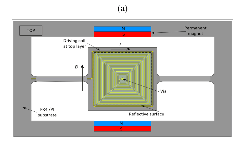
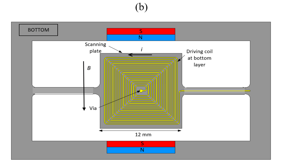
Figure 1: Coil design shown in the (a) top and (b) bottom layers of the PCB with a connection via placed at the center of the scanning plate.
In this paper, the use of PI substrate for scanning micro-mirrors is novel and is here compared to FR4-based substrates. Its low elastic modulus leads to enhanced scanning angles, which is advantageous for applications such as LiDAR. This choice of substrate is also attractive as a low-cost alternative to MEMS-based micro-mirror designs. Furthermore, novel electronic interface circuitry is presented for the eventual positional control of the micro-mirror without the requirement of additional sensors.
2. Micro-mirror Mechanical Design
2.1. Numerical Design
The PCB-based micro-mirrors consist of three main elements: the actuation coil, a pair of torsional springs, and the reflective aperture area. The mirrors are designed to operate at resonance in the out-of-plane torsional mode.
The resonant frequency fr of the micro-mirror is given by [26]:
$$
f_r = \frac{1}{2\pi}\sqrt{\frac{k_t}{I_m}}
\tag{3}
$$
where kt is the torsional stiffness of the springs and Im is the moment of inertia of the mirror plate around the rotational axis.
In this case, for straight springs, the torsional stiffness kt is given by:
$$
k_t = 2G \frac{J}{l_s}
\tag{4}
$$
where G is the material shear modulus and ls is the spring length. The shape-factor term J for a spring having a rectangular cross-section, of width ws and thickness ts, (ws ≥ ts), is given by [26]:
$$
J = w_s t_s^3 \left[ \frac{1}{3} – \left( 0.21 \frac{t_s}{w_s} \left( 1 – \frac{t_s^4}{12 w_s^4} \right) \right) \right]
\tag{5}
$$
The shear modulus G can be inferred from the Young’s modulus E and Poisson ratio ν, using [26]:
$$
G = \frac{E}{2(1+\nu)}
\tag{6}
$$
The moment of inertia Im of the rectangular mirror plate having width Wm, length Lm, thickness Tm, and density ρm is given by:
$$
I_m = \frac{\rho_m L_m W_m T_m}{12} (W_m L_m)^2
\tag{7}
$$
The various dimensions that determine the mirror’s resonant frequency are depicted in Figure 3.
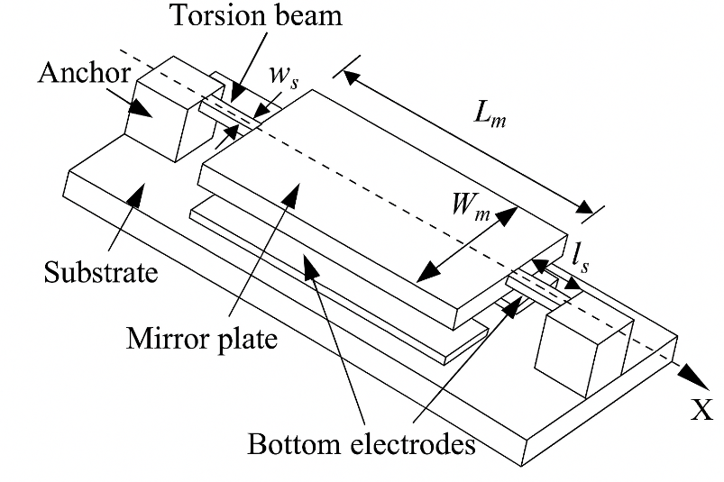
Straight torsional beams with rectangular cross-sections are used to support the 10 mm by 10 mm mirror plate, where the spring width and length were selected to achieve the target resonant frequency.
The coil consists of two layers of copper turns in a rectangular spiral shape on both sides of the substrate. Different coil designs were considered with the aim of achieving the maximum magnetic coupling and the lowest actuation voltage. The external connections to the two coil layers are routed via the torsional springs. The two coil layers are connected in series using a via placed at the center of the mirror plate area.
The coil designs (based on Figures 1 and 2) that have been investigated in this work are presented in Table 2. In each case, the copper thickness is fixed by the PCB process at 35 µm for both the FR4 and PI-based mirror substrates.
Table 2: Coil configurations examined in this study.
| Coil trace width (a) (mm) | Total coil trace length (mm) | Number of turns/layer | DC Resistance (Ω) |
|---|---|---|---|
| 0.503 | 278.5 | 5 | 0.265 |
| 0.152 | 591.7 | 15 | 1.878 |
| 0.102 | 712.5 | 20 | 2.261 |
| 0.102 | 899.7 | 25 | 4.725 |
The device dimensions for the FR4 and the polyimide PCB-based mirrors were calculated based on the material properties shown in Table 3.
Table 3: Material properties used for mechanical design.
| Property | FR4 | Polyimide | Polycarbonate (mirror) |
|---|---|---|---|
| Density (g/cm³) | 1.85 | 1.42 | 1.2 |
| Young’s Modulus (GPa) | 22 | 3 | 2.4 |
| Poisson ratio | 0.11 | 0.34 | 0.38 |
The resulting PCB design for three different electromagnetic scanning micro-mirrors is shown in Figure 4. These designs have the same dimensions, but different coil designs.
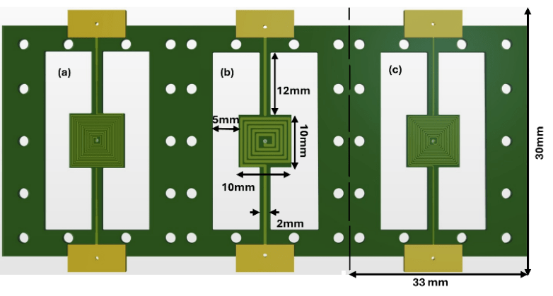
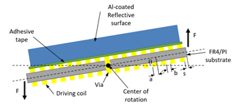
Figure 5 shows the vertical cross-section of the designed micro-mirror. The PCB substrate and the coil were fabricated using the PCBway prototyping service. The reflective aluminum (Al) coated polycarbonate layer was extracted from a compact disc (CD) and attached to the PCB substrate using double-sided tape.

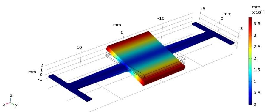
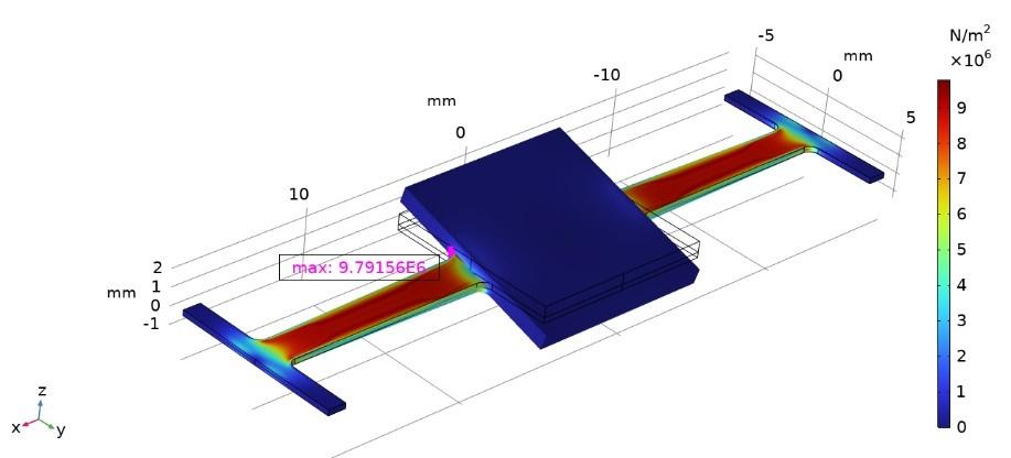
The mechanical design was verified by performing modal finite element analysis (FEA) using COMSOL Multiphysics to determine the torsional mode resonant frequency (refer to Figure 6). These simulations were also used to verify that adjacent modal frequencies were adequately separated, thus preventing spurious excitation of unwanted modes. Static structural FEA simulations were also carried out to determine the von Mises stress distribution and ensure that these are well below the maximum yield strength of the substrate material (refer to Figure 7). These simulations were carried out by applying an angular acceleration corresponding to an optical scanning angle amplitude of 40° at the first torsional modal frequency. Both simulations were carried out using swept hexahedral elements with 5 elements across the thickness of the device polymer layer and with fixed constraints (for the 6 degrees of freedom) applied to edge boundaries of the anchors attached to the torsional springs. The glass mirror was included in the simulations as this affects the moment of inertia. In each case, linear isotropic elastic material properties were considered: this is justified on the assumption that the maximum elastic strain developed at the maximum scanning angle is within the linear elastic limit of the polymer material. A mesh convergence study was performed to ensure that a negligible change in the maximum von Mises stress is obtained with further mesh refinement. The maximum von Mises stress values are 9.79 MPa and 79.95 MPa for the PI and FR4-based micro-mirrors, respectively. These von Mises stress values correspond to 4.2% and 21% of the respective material’s ultimate tensile strength.
2.2. Complete Micro-Mirror Assembly
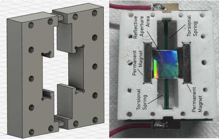
The PCB-based micro-mirror was assembled, together with a pair of neodymium permanent magnets, in a 3D-printed polylactide (PLA) housing, as shown in Figure 8. The PCB substrate is clamped between two 3D-printed PLA blocks. The air gap between the magnets and the mirror plate was set to be 1 mm. This value was chosen as a compromise between mechanical tolerances and optimal electromagnetic coupling.
3. Micro-mirror Analytical, FEA, and Characterization Results
During characterization, the actual value of the mechanical resonant frequency of the mirror was obtained by manually applying an impulse mechanical torque and observing the resulting coil voltage on an oscilloscope, as shown in Figure 9.
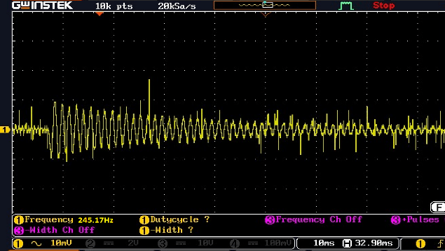
While eight micro-mirror prototypes were fabricated, a summary of the analytical, FEM, and experimental results for the two best-performing prototypes are presented in Table 4. Note that the values of the actual fabricated substrate thickness t (FR4 0.23 mm and PI 0.26 mm) are lower than the intended nominal value (0.3 mm), and therefore, simulations were also repeated for the actual thickness. Table 4 shows the maximum scanning angles achieved for each substrate and the resonant frequency fr. The variation between the simulated and actual values of fr is attributed to the manufacturing tolerances as well as material property variations. In this case, the measured resonant frequency was determined experimentally as the frequency which maximized the scanning angle. Table 4 also shows the simulated adjacent mode resonant frequency of the micro-mirror, which corresponds to the up-down translational mode.
Table 4: Mirror analytical, simulation, and measured results.
| Parameter | Substrate Type | |
|---|---|---|
| FR4 | PI | |
| Analytical (t = 0.3 mm) fr (Hz) | 692.3 | 321.7 |
| Simulated (t = 0.3 mm) fr (Hz) | 792.9 | 285.2 |
| Simulated fr (corrected actual t) (Hz) | 569.3 | 261.2 |
| Simulated adjacent modal frequency (Hz) | 440.3 | 180.1 |
| Measured resonant frequency fa (Hz) | 550 | 250 |
| Measured optical scanning angle (°) | 31.3 | 52.1 |
Table 5 presents the measured optical scanning angle achieved for eight micro-mirror prototypes featuring coils of different number of turns per layer (n) implemented using either FR4 or PI substrate (sub). The optical scanning angle is four times the mechanical scanning angle [27]. Table 5 also provides the coil dimensions (trace width a and trace spacing b) together with the actuation frequency fa as well as the coil current. In all cases, the driving coil current was kept within the same range for ease of comparison. Coil designs 3 and 8, which have the highest number of turns, resulted in the highest optical scanning angle for the FR4 and PI substrates, respectively. This is expected due to the higher electromagnetic coupling, as can be inferred from (2).
Table 5: Characterization results for the fabricated mirrors having different substrates and actuating coil designs.
| Coil | Sub | n | Trace width a, mm | Trace spacing b, mm | Coil mA | fa, Hz | θ (°) |
|---|---|---|---|---|---|---|---|
| 1 | FR4 | 5 | 0.503 | 0.203 | 265 | 650 | 5.5 |
| 2 | FR4 | 15 | 0.152 | 0.152 | 250 | 550 | 11.4 |
| 3 | FR4 | 20 | 0.102 | 0.102 | 226 | 550 | 31.3 |
| 4 | PI | 5 | 0.503 | 0.230 | 270 | 300 | 20.4 |
| 5 | PI | 15 | 0.152 | 0.152 | 235 | 250 | 27.6 |
| 6 | PI | 20 | 0.102 | 0.125 | 260 | 250 | 49.4 |
| 7 | PI | 25 | 0.102 | 0.102 | 260 | 250 | 52.1 |
4. Electronic Interface Design
4.1. Functional Description
The electronic interface for the scanning mirror is designed around the STM32L432KC microcontroller (MCU), as shown in the block diagram of Figure 10. The STM32L432KC can operate at an 80 MHz clock speed and has an in-built 12-bit ADC and complementary PWM channels. The PWM outputs are useful for generating the required signals to drive the actuation coil of the micro-mirror.
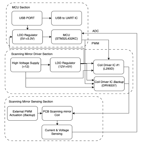
An H-bridge driver configuration was chosen to maximize the coil driving voltage and minimize the power supply voltage requirement. For this purpose, two different alternative driver integrated circuits were investigated, one based on the MOSFET DRV8837 and the other based on the bipolar L293. The interface also includes provision of USB communication for configuration purposes, as well as real-time measurement of the actuation coil current and voltage. Coil current sensing is achieved via the use of the INA241 sense amplifier, while voltage sensing is carried out using a potential divider. These analogue feedback signals are connected to two ADC channels of the MCU, with the aim of eventually determining the scanning mirror’s angular position accurately without the use of additional optical sensors.
4.2. PCB Design
The prototype PCB development was split into three sub-systems to facilitate the testing and verification process: these consist of the MCU PCB, coil driver PCB, and the coil voltage and current sensing PCB. Each PCB section has a size of 30 mm by 30 mm and is stacked on one another.
4.2.1. Microcontroller PCB
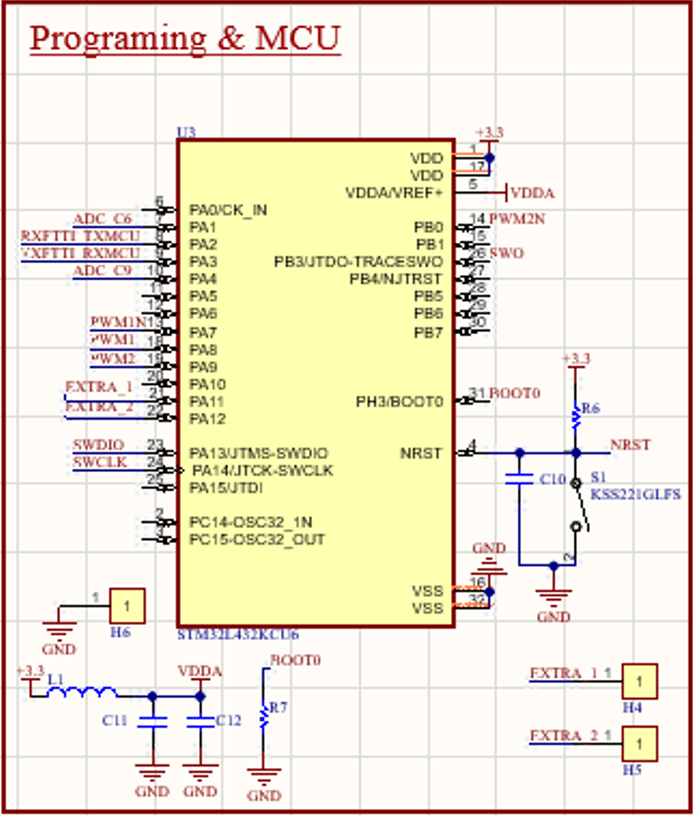
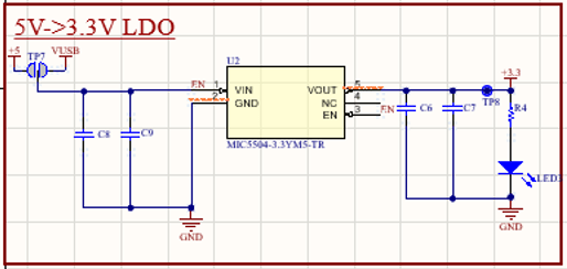
The main function of the MCU PCB is to generate complementary PWM coil driving signals whose parameters, namely the frequency and duty cycle, are controlled via a personal computer using commands issued over the UART interface. This circuitry is built around the STM32L432KC microcontroller, as shown in Figure 11 (a). The MCU requires a 3.3 V supply, obtained via a low-dropout (LDO) regulator that lowers the 5 V USB supply voltage rail, as shown in Figure 11(b). The USB port allows a maximum sinking current of 500 mA, which is sufficient to power the MCU, LDO, and the FT232. However, the possibility of an external 5 V supply was included.
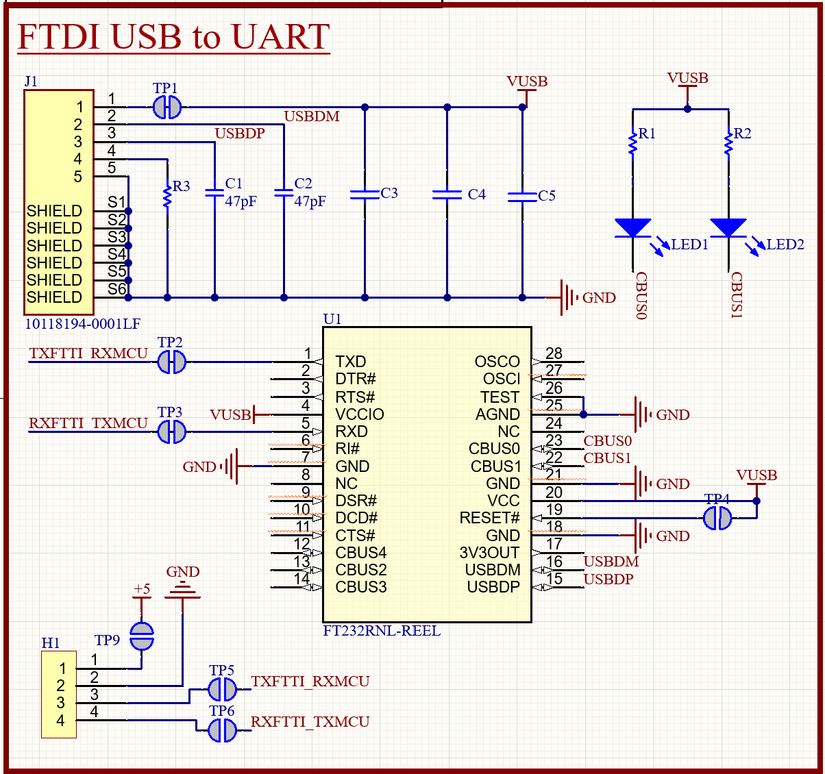
The FT232 is used as the USB-to-UART interface. The interfacing connections with the FT232 IC are shown in Figure 11(c). Two LEDs were connected to the data bus via pins 22 and 23 to provide visual feedback of the data transmission. Power supply stability was ensured via decoupling capacitors, which were placed physically close to the various ICs.
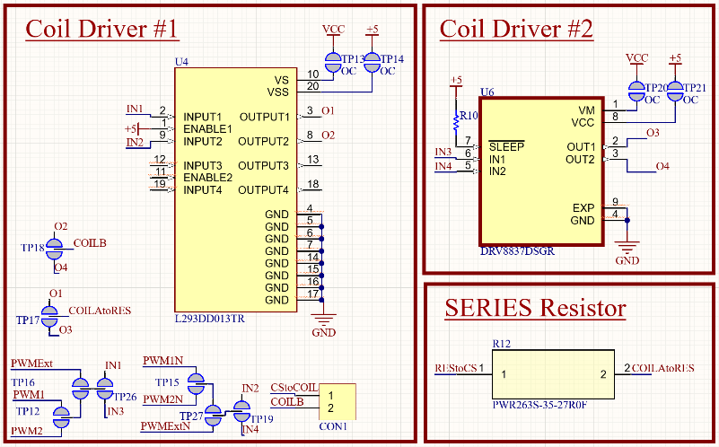
4.2.2. Coil Driver PCB
The coil actuation PCB makes use of either the L293D or the DRV8837 motor driver ICs. The L293D is a quadruple high-current half-H bridge driver that operates between 4.5 V and 36 V and can drive currents up to 600 mA in both directions. The control voltage range is 1.8 V to 7 V and is therefore compatible with the STM microcontroller. The DRV8837, on the other hand, is an H-bridge driver that uses N-channel power MOSFETs with an internal charge pump, providing an output current of up to 1.8 A and requiring a smaller PCB footprint.
4.2.3. Coil Sensing PCB
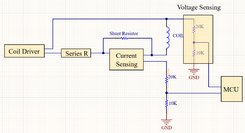
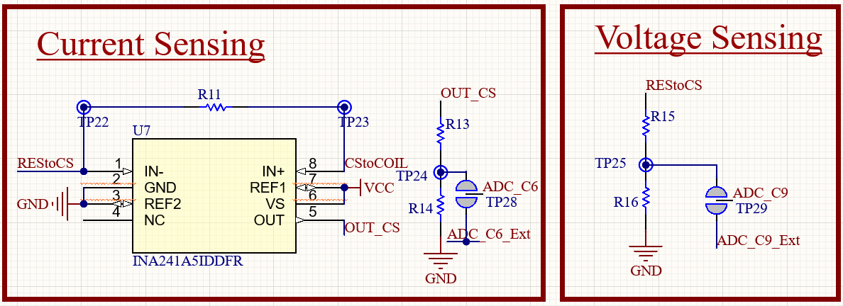
This PCB provides sensing of the mirror coil voltage and current feedback signals, which are fed back to the MCU via the ADC inputs. The INA241 amplifier is used for current measurement via a shunt resistor and was chosen due to its low input offset as well as high common mode rejection ratio (CMRR), which is crucial for the accurate detection of the coil current waveform, which is superimposed on the high coil drive voltage swing. Voltage sensing is achieved via a resistive potential divider. This circuitry is shown in Figure 13.
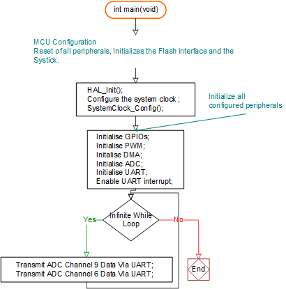
4.3. Firmware Design
The MCU firmware was designed to support various functions, including initialization of GPIO ports, PWM parameters for coil driving, direct memory access (DMA) and ADC, and Figure 13: Coil voltage and current sensing feedback circuitry.
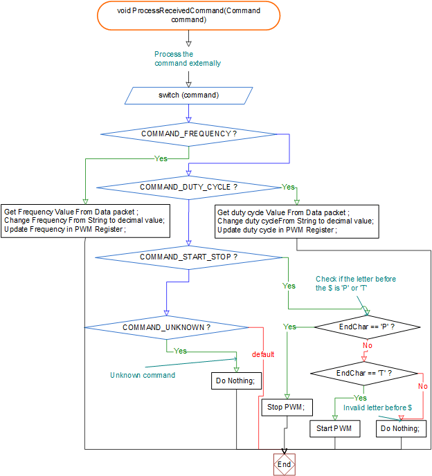
UART. In addition, the MCU transmits the sensed coil current and voltage signals via the UART. The main firmware loop, which takes care of these processes, is shown in Figure 14. A UART-based protocol, shown in Figure 15, was developed, which enables setting up of the PWM frequency and duty cycle, as well as enabling and disabling of the PWM signals. A user interface was developed using C# to be able to control the PWM signal frequency and the duty cycle. The PWM frequency is configurable from 50 Hz to 10 kHz.
5. Characterization of Scanning Angle variation with Duty Cycle
As explained in Section 4, the MCU design allows for PWM frequency and duty cycle control. Frequency control allows the mirror to be operated at resonance and caters for necessary tuning to compensate for process-related geometric variations as well as material property variations, which can also occur with temperature changes. It should be noted that FR4 and PI substrates are prone to mechanical property changes [3], which can occur due to aging related to mechanical stresses as well as exposure to elevated temperatures.
Duty cycle control allows for control of the scanning angle by effectively varying the electrical energy input to the actuation coil. The effect of duty cycle on scanning angle was investigated by varying the duty cycle from 10% to 50%. The corresponding scanning angle was geometrically calculated using the setup shown in Figure 16, consisting of a laser source and a projection screen. In this case, the PI-based micro mirror operating at a resonant frequency of 250 Hz is characterized.
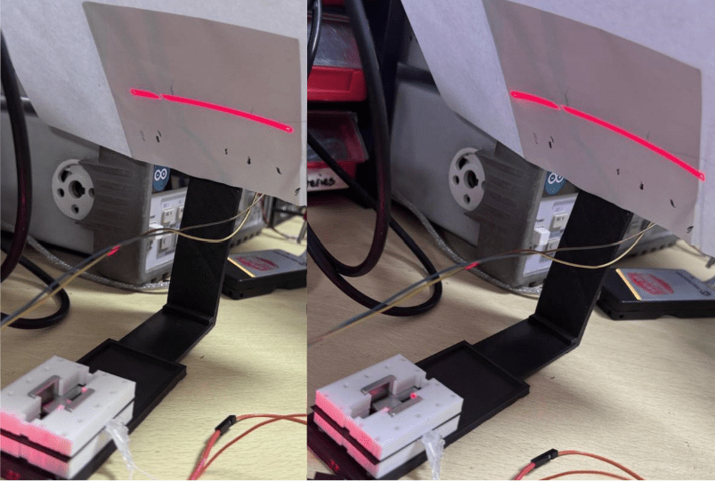
Table 6 shows the corresponding scanning angles achieved at different values of duty cycle, as well as the corresponding recorded average coil voltage and current for the PI-based micro-mirror. A 22 mΩ shunt resistor is used in this case, followed by a voltage amplification of 200. The corresponding plot for the variation of the optical scanning angle with duty cycle is shown in Figure 17. As expected, the response exhibits a monotonically increasing scanning angle with duty cycle. However, non-linearity in the relationship can be observed, possibly arising from variations in coil resistance and material properties due to an elevated operating temperature at the higher duty cycle values, resulting from the coil I2R losses, as well as other mechanical non-linearities.
Table 6: PI-based micro-mirror experimental results: scanning angle, coil voltage, and current at different values of applied voltage duty cycle, operated at a frequency of 250 Hz.
| Duty Cycle (%) | Optical Scanning Angle (°) | Average Coil Voltage (V) | Average Amplified Current-Sensing Shunt Voltage at the ADC Input (V) | Average Coil Current (computed) (mA) |
|---|---|---|---|---|
| 10 | 18.46 | 0.926 | 0.979 | 222 |
| 20 | 30.31 | 1.054 | 1.383 | 314 |
| 30 | 34.27 | 1.147 | 1.645 | 373 |
| 40 | 42.74 | 1.222 | 1.822 | 414 |
| 50 | 52.10 | 1.279 | 1.997 | 454 |
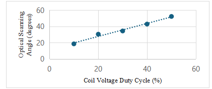
Table 7 presents a comparison of the key parameters with other electromagnetically actuated FR4-based micro-mirror designs. As expected, the novel PI-substrate lends itself to a higher optical scan angle when compared to the FR4-based mirrors, for the same driving current and spring geometry. This is expected due to its lower elastic modulus. Notable exceptions are FR4-based micro-mirrors employing serpentine springs, which have a lower effective spring constant for the same elastic modulus. This higher scanning angle is achieved at the expense of a slightly more complex fabrication process, which also complicates the electrical routing design to the actuation coil.
Table 7: Comparison with previous electromagnetically actuated micro-mirror designs with different spring designs (rectangular / serpentine).
| c | Substrate | Aperture (mm) | Res. Freq. (Hz) | Opt. Scan Angle (°) | Spring Type | Drive Current (mA) | Coil Resistance (Ω) / Number of Turns |
|---|---|---|---|---|---|---|---|
| [3] | FR4 | 12 x 12 | 361.8 | 11.2 | Rect. | 115 | 3.7 / 11 |
| [4] | FR4 | 5 x 5 | 1787 | 19.9 | Rect. | 250 | N/A |
| [4] | FR4 | 5 x 5 | 417.4 | 140 | Serp. | 250 | N/A |
| [4] | FR4 | 8 x 8 | 807 | 30 | Rect. | 250 | N/A |
| [5] | FR4 | 12 x 12 | 190 | 52 | Serp. | 100 | 3.13 / 16 |
| This work | FR4 | 10 x 10 | 250 | 31.3 | Rect. | 226 | 2.26 / 20 |
| This work | PI | 10 x 10 | 550 | 52.1 | Rect. | 260 | 4.73 / 25 |
6. Conclusion and Future Work
This work has demonstrated the feasibility of using FR4 and polyimide substrates to fabricate electromagnetic scanning mirrors through standard PCB processes. The resulting prototypes integrate planar copper coils, torsional springs, and reflective plates into compact devices that can be produced at a fraction of the cost of commercial MEMS mirrors, especially for low-volume applications. The integration of low-cost electronics, including a microcontroller, H-bridge drivers, and current/voltage sensing, may eventually be utilized for accurate positional control of the micro-mirror without the need for additional sensors.
The results clearly establish polyimide as the more suitable substrate for wide-angle scanning, with maximum optical deflections of up to 52.1°, achieved at a resonant frequency of around 250 Hz. This is the result of its lower value for the Young’s modulus. While FR4 mirrors exhibited higher resonant frequencies and greater rigidity, their smaller deflections limit their applicability to systems requiring narrow scanning angles. In both cases, the prototypes confirmed the practicality of PCB-compatible designs for optical beam steering applications. Furthermore, it was noticed that PI-based micromirrors tended to achieve more repeatable results and were less susceptible to thermally induced stress. The repeatability of PI-based micromirrors is possibly explained by the fact that polyimide films tend to be more homogeneous than FR4 substrates. An interesting investigation would be a PI-based design employing serpentine spring structures, where a further enhancement of the optical scan angle for the same actuation current is expected.
Another consideration is system robustness. Unlike silicon MEMS mirrors, which are prone to brittle fractures, PCB-based mirrors are relatively robust under mechanical shock and vibration. The use of 3D-printed holders further contributes to mechanical stability, though long-term reliability testing remains necessary.
Despite these promising results, several limitations remain. The high-power consumption of the prototypes, of the order of 1.3 W, must be addressed to enable wider adoption in portable or battery-powered systems. Coil optimization, magnetic field enhancement, and resonant drive techniques represent promising directions to improve efficiency. Thermal effects also warrant closer study, particularly in polyimide mirrors, where repeated thermal cycling may induce material fatigue or delamination of copper traces. Therefore, reliability testing over extended periods is also necessary to evaluate the long-term durability of the substrates and coil under cyclic loading
This work can contribute to further development within the area of low-cost scanning micro-mirrors. Dual-axis scanning mirrors, fabricated on polyimide, could be developed to provide full two-dimensional beam steering for advanced LiDAR systems. Closed-loop control schemes based on the existing voltage and current sensing still need to be developed and evaluated using position sensors or optical feedback to enhance accuracy and stability, particularly in environments prone to vibration. Integration with existing LiDAR modules and field testing in automotive or robotic platforms will provide a more comprehensive assessment of system performance. Finally, further miniaturization and optimization of the drive electronics could reduce the footprint and improve overall efficiency.
In conclusion, PCB-compatible electromagnetic scanning mirrors based on PI or FR4 substrates represent a promising low-cost alternative to conventional silicon MEMS devices. They offer wide scanning angles, low resonant frequency operation, and scalable manufacturability, opening new opportunities for affordable LiDAR, biomedical imaging, and display technologies.
- N. Dimech, I. Grech, R. Farrugia, O. Casha, J. Micallef, B. Portelli, “Design of a low-cost resonant electromagnetic scanning mirror and its drive/sense circuitry,” in IEEE International Conference on Electronics, Circuits and Systems (ICECS), Nancy, France, 2024 doi: 10.1109/ICECS61496.2024.10848840
- L. Haitao, W. Zhiyu, L. Dongling, H. Jian, Z. Ying, G. Pengfei, “A Control and Detecting System of Micro-Near-Infrared Spectrometer,” MDPI Micromachines, 9(4), 152, 2018, doi: 10.3390/mi9040152
- H. Lei, Q. Wen, F. Yu, Z. Y., “Fr4-based electromagnetic scanning micromirror integrated with angle sensor,” MDPI Micromachines, 9(5) .doi: 10.3390/mi9050214, p. 214, 2018.
- H. Urey, S. Holmstom, A. Yalcinkaya, “Electromagnetically actuated FR4 scanners,” IEEE Photonics Technology Letters, 20(2), 30-32, 2008, doi: 10.1109/LPT.2007.911522
- R. Farrugia, B. Portelli, I. Grech, J. Micallef, O. Casha, E. Gatt, “An out-of-plane FR4-mems scanning grating for NIR spectrometer,” in IEEE Symposium on Design, Test, Integration and Packaging (DTIP), Pont-a-Mousson, 2022, doi: 10.1109/DTIP56576.2022.9911731
- Y. Zhou, Q. Wen, T. Yang, “Modeling of MOEMS electromagnetic scanning grating mirror for NIR micro-spectrometer,” AIP Advances, 6(2). doi: 10.1063/1.4942973, 2016.
- L. Haitao, N. Shuoran, Z. Ying, Y. Liwei, “Control and Signal Acquisition System of Broad-Spectrum Micro-Near-Infrared Spectrometer Based on Dual Single Detector,” MDPI Micromachines, 12(6). doi: 10.3390/mi12060696, 2021.
- D. Hah, S.-Y. Huang, J.-C. Tsai, H. Toshiyposhi, M. Wu, “Low-voltage, large-scan angle MEMS analog micromirror arrays with hidden vertical comb-drive actuators,” IEEE Journal of Microelectromechanical Systems, 13(2), 279-289, 2004, doi: 10.1109/JMEMS.2004.825314
- B. Stann, J. Dammann, M. Giza, P. Jian, W. Lawler, H. Nguyen, L. Sadler, “MEMS-scanned ladar sensor for small ground robots,” in SPIE Defense, Security, and Sensing, 7684, Florida, US, 2010, doi: 10.1117/12.850388
- D. Wang, C. Watkins, H. Xie, “MEMS Mirrors for LiDAR: A Review,” Micromachines, 11(5), 2020, doi: 10.3390/mi11050456
- M. Ahmad, M. Bahri, M. Sawan, “MEMS Micromirror Actuation Techniques: A Comprehensive Review of Trends, Innovations, and Future Prospects,” MDPI Micromachines, 15(10), 2024, doi: 10.3390/mi15101233
- T. Kaiser, B. J. Lutzenberger, R. Friholm, P. Himmer, D. Dickensheets, “Silicon Nitride Biaxial Pointing Mirrors with Stiffening Ribs,” in Proc. of SPIE 4561 – MOEMS and Minaturized Systems II., 2001, doi:10.1117/12.443096
- J. Buhler, J. Funk, J. Korvink, F.-P. Steiner, P. Sarro, H. Baltes, “Electrostatic aluminum micromirrors using double-pass metallization,” IEEE Journal of Microelectromechanical Systems, 6(2), 126-135, 1997, doi:10.1109/84.585790
- S.-K. Chung, J.-W. Shin, Y.-K. Kim, B.-S. Han, “Design and fabrication of micromirror supported by electroplated nickel posts,” Sensors and Actuators A: Physical, 54(1-3), 464-467, 1996, doi: 10.1109/SENSOR.1995.717181
- Q. Wen, H. Lei, F. You, D. Li, Y. She, J. Huang, L. Huang, Z. Wen, “Investigation of electromagnetic angle sensor integrated in FR4-based scanning micromirror,” Applied Sciences, 8(12), 2412, 2018, doi: 10.3390/app8122412
- S. Kim, C. Lee, J. Kim, G. Lim, J. Kim, C. Kim, “A 2-axis Polydimethylsiloxane (PDMS) based electromagnetic MEMS scanning mirror for optical coherence tomography,” in SPIE Conference on Advanced Biomedical and Clinical Diagnostic and Surgical Guidance Systems, 2016 doi:10.1117/12.2211928
- S. Lee, M. Kim, J. An, M. Jun, S. Yang, L. J.H., “Polymeric (SU-8) Optical Microscanner Driven by Electrostatic Actuation,” in IEEE 22nd International Conference on Micro Electro Mechanical Systems, Sorrento, Italy, 2009, doi: 10.1109/MEMSYS.2009.4805543
- T. Liu, A. Svidunovich, B. Wollatnt, D. Dickensheets, “MEMS 3-D Scan Mirror with SU-8 Membrane and Flexures for High NA Microscopy,” Journal of Microelectromechanical Systems, 27(4), 719-729, 2018, doi: 10.1109/JMEMS.2018.2845375
- A. Bhattacharya, Introduction to MEMS Design, Springer Sceince & Business Media, 2004.
- T.-I. Lee, C. Kim, M. Kim, T.-S. Kim, “Flexural and tensile moduli of flexible FR4 substrates,” Polymer Testing (Elsevier), 53, 70-76, 2016, doi: 10.1016/j.polymertesting.2016.05.012
- Dupont(TM), “Dupont Kapton – Summary of Properties,” Dupont(TM). https://www.dupont.com/content/dam/electronics/amer/us/en/electronics/public/documents/en/EI-10142_Kapton-Summary-of-Properties.pdf, 2022.
- A. Kurhekar, S. Duttagupta, “On calculation of elastic properties in silicon and germanium single crystals,” in 4th International Conference on Electronics and Communication Systems (ICECS), Coimbatore, India, 2017, doi: 10.1109/ECS.2017.8067870
- E. Pengwang, K. Rabenorosoa, M. Rakotondabe, N. Andreff, “Scanning Micromirror Platform Based on MEMS Technology for Medical Application,” Micromachines (Special issue on Micro/nano Robotics, 7(2), 2016, doi: 10.3390/mi7020024
- A. Ren, Y. Ding, H. Yang, T. Pan, Z. Zhang, H. Xie, “A Large-Scan-Range Electrothermal Micromirror Integrated with Thermal Convection-Based Position Sensors,” MDPI Micromachines, 8(15), 1017, 2024, doi: 10.3390/mi15081017
- K. Ruotsalainen, D. Morits, O. Ylivaara, J. Kyynarainen, “Resonating AlN-thin film MEMS mirror with digital control,” SPIE Journal of Optical Microsystems, 2(1), 2022, doi:10.1117/1.JOM.2.1.011006
- C. Leondes, Mems, Nems, (1) Handbook Techniques and Applications Design Methods, Springer, 2006.
- K. Meinel, M. Melzer, C. Stoeckel, A. Shaporin, R. Forke, S. Zimmermann, “2D Scanning Micromirror with Large Scan Angle and Monolithically Integrated Angle Sensors Based on Piezoelectric Thin Film Aluminum Nitride,” MDPI Sensors (Special Issue on MEMS Actuators and Sensors), 20(22), 2020, doi: 10.3390/s20226599