
The Impact of Antenna Design on Breast Microwave Imaging

Adv. Sci. Technol. Eng. Syst. J. 11(3), 1–8 (2026);
 DOI: 10.25046/aj110301
Breast microwave sensing (BMS) systems offer a low-cost and efficient alternative to current breast cancer screening methods. However, reported performance varies widely due to differences in system configuration, antenna design, measurement protocols, and image reconstruction techniques. This study evaluates the impact of antenna design on key image quality metrics using a controlled experimental platform. Spatial resolution, signal-to-noise ratio (SNR), signal-to-clutter ratio (SCR), intensity shift invariance, and contrast resolution were assessed using six antennas: a horn, a Vivaldi, and four ultra-wideband (UWB) flexible printed circuit board (PCB) antennas. These antennas were selected to assess the effects of antenna type, beam pattern, gain, and physical size. By isolating antenna characteristics while maintaining all other imaging parameters constant, this work provides a systematic comparison of antenna design factors whose individual contributions have not been clearly established in the existing BMS literature. All measurements were acquired using a single imaging chamber with a consistent frequency range, angular sampling, and delay-and-sum reconstruction technique. While higher gain generally improved image quality for high-contrast targets, the results indicate that the antenna footprint and beam pattern also play significant roles. In particular, small, compact omnidirectional PCB antennas with 6 dBi gain may improve spatial resolution and contrast compared to a horn antenna with 12 dBi gain. Directional antennas exhibited reduced sensitivity, with horn antenna beam patterns affecting contrast and spatial uniformity. These findings highlight the importance of considering multiple antenna design parameters, rather than only gain, when optimizing BMS systems for robust, portable deployment in low-income and remote regions.
1. Introduction
This paper is an extension of the work originally presented at the 2025 IEEE 20th International Symposium on Antenna Technol-ogy and Applied Electromagnetics (ANTEM) [1].
Breast cancer remains the most commonly diagnosed cancer among women, and early detection is crucial for successful treatment [2, 3]. However, access to screening programs is limited in low- and middle-income countries (LMIC) [4] and in remote areas and among those of lower socioeconomic status in developed countries [5, 6]. This leads to large, palpable tumours at diagnosis and contributes to higher mortality rates in these individuals [4, 5, 7]. Current screening methods lack portability and are of limited use in low-income and remote regions because they require robust capital and human infrastructure.
X-ray mammography remains the primary screening tool used for breast cancer detection. However, the use of ionizing X-rays poses a small cancer risk, limiting the recommended screening to every second year for women over 40 [8]. Additionally, X-ray mammography is limited in portability due to the fragile equipment and the need for a trained technologist to operate it and a radiologist to interpret the results. MRI is often used as a secondary imaging tool and to screen high-risk women [9], however, its high cost, lower specificity [10] and large size make it unsuitable for screening, particularly in LMIC. Ultrasound is the most portable of the systems. Still, it is operator-dependent, requiring skilled personnel to acquire and interpret the images, limiting its use in remote regions where human infrastructure may be insufficient.
Studies into breast microwave sensing (BMS) have shown its potential as an alternative or complementary screening tool [11, 12, 13]. BMS detects abnormalities by utilizing the intrinsic contrast in microwave properties between healthy and cancerous tissue. Its low cost, compact size, use of non-ionizing radiation, and straightforward imaging protocol make it well-suited for routine and frequent scanning in remote and low-income areas.
Typical BMS systems illuminate the breast with microwaves using an antenna and VNA. However, existing systems yield varying results due to differences in antenna array configuration, antenna design, measurement protocols, and image reconstruction methods [11, 14, 15]. These differences make it difficult to optimize a system’s design.
This work uses a versatile BMS system to evaluate and compare the impact of antenna design parameters whose influences remain insufficiently understood in the existing literature. We hypothesize that antennas with higher gain should improve signal-to-noise ratio (SNR) and signal-to-clutter ratio (SCR) for high-contrast objects. In contrast, antennas with broader beam patterns and smaller physical footprints may provide more spatially uniform responses and improved performance for heterogeneous breast phantoms. By maintaining a consistent setup, housing, measurement protocol, and reconstruction method across different antenna types, we can evaluate the impact of specific antenna characteristics. Scans of metal rods and breast phantoms were performed to evaluate each an-tenna’s performance. Five image quality metrics were investigated: spatial resolution, signal-to-noise ratio (SNR), signal-to-clutter ratio (SCR), contrast resolution, and intensity shift invariance. Un-derstanding the impact of antenna type, gain, aperture size, and beam pattern will facilitate the optimization of an efficient, low-cost BMS system.
2. Methods
2.1. Imaging system and antenna specifications
A BMS system was designed for multi-analysis evaluation and comparison studies (Fig. 1). The system features a 20 cm diameter cylindrical imaging chamber with a rotational platform, enabling radar measurements to be performed at various angles of incidence. The system has a single aperture that accommodates antennas of various types and sizes. Its versatile design supports the use of different VNAs and antennas, facilitating evaluation and
comparison studies.
For this work, a Copper Mountain C1209 VNA was paired with different antenna types to isolate the effects of antenna design. Six antennas, as detailed in Table 1, were used in this work:
- Horn: A-Info, LB-20200-SF [16]
- Vivaldi: Applied EM Innovations, UWB700-D [17]
- FlexPCB (A): Taoglas, FXUB85 [18]
- FlexPCB (B): Siretta, Echo47 [19]
- FlexPCB (C): Taoglas, FXUB66 [20]
- FlexPCB (D): Siretta, Echo44 [21]
Table 1: Specifications of the six antennas used in this work.
| Antenna | Gain (dBi) | Size (cm) (w × h × d) |
Beam Pattern |
|---|---|---|---|
| Horn | 12 | 10 × 8 × 13 | 16° and 18° 3 dB beamwidth (E- and H-plane) |
| Vivaldi | 8 | 0.6 × 19 × 20 | 34° and 31° 3 dB beamwidth (E- and H-plane) |
| Flex PCB (A) | 3 | 2 × 16 × 0.2 | Omnidirectional |
| Flex PCB (B) | 5.9 | 2 × 17 × 0.2 | Omnidirectional |
| Flex PCB (C) | 6.9 | 5 × 12 × 0.2 | Omnidirectional |
| Flex PCB (D) | 6.4 | 1.4 × 5 × 0.2 | Omnidirectional |
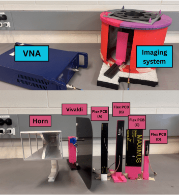
These antenna types were selected because they are suitable for BMS, and the horn and Vivaldi antennas have been used in our lab for several years. The specific designs were chosen to provide insight into the effect of antenna type, gain, aperture size, and beam pattern. Notably, the beam pattern varies by antenna type: the horn and Vivaldi antennas exhibit directional patterns, while the flexible PCB antennas provide approximately omnidirectional patterns.
Four different flexible PCB antennas were compared to reduce the influence of the beam pattern and assess the impact of gain and physical antenna size. The flexible PCBs A and B have similar beam patterns and sizes, providing insight into the effects of gain. The flexible PCBs B–D have similar beam patterns and gains (≈ 6-7 dBi), providing insight into the effect of physical antenna size. The overlapping frequency range of all antennas is 2–7 GHz.
2.2. Data collection and image quality metrics
To evaluate the antenna’s effects, the system parameters were maintained consistently across all measurements. S11 measurements were collected every 10 MHz from 2–7 GHz using the Copper Mountain VNA (C1209) with an output power of 5 dBm. For each scan, the object under test was rotated to 24 angular positions, separated by 15 degrees. All reconstructions were performed using the same image grid, frequency range, and delay-and-sum parameters.
Before data acquisition, the VNA was calibrated using the Cop-per Mountain (ACM2509) Automatic Calibration Module. For each antenna, a reference measurement of the empty or adipose-filled chamber was acquired and subtracted from the measured response to reduce static reflections and system artifacts. Unless otherwise stated, no antenna-specific image normalization was applied before metric calculation, such that differences in image intensity reflect the combined effects of antenna coupling, radiation pattern, and received signal strength.
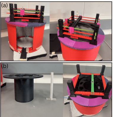
Two sets of measurements were performed to evaluate image quality. First, measurements were conducted using a metal rod (Fig. 2a) as a high-contrast point target. A 3D printed position-ing system was used to place the rod at the following coordinates: (0 cm, 0 cm), (0 cm, 1 cm), (0 cm, 2 cm), (0 cm, 3 cm), (0 cm, 4 cm), (0 cm, 5 cm), (1 cm, 1 cm), (2 cm, 2 cm), (3 cm, 3 cm), (4 cm, 4 cm), (5 cm, 5 cm).
Next, measurements were performed on a cylindrical breast phantom designed to represent healthy (adipose and fibroglandular tissue) and cancerous tissue (Fig. 2b). Two scans were performed by filling a thin (1 cm) cylinder with (1) tumour-mimicking material and (2) fibroglandular-mimicking material. The breast mimicking material used in this study replicates that described in [22]. This cylinder was then positioned inside a larger 10 cm cylindrical phan-tom filled with adipose-mimicking material. A reference scan of the adipose-filled shell was subtracted from the scans to suppress the “skin” response and highlight the tumour and fibroglandular signal responses.
Radar images were reconstructed using a delay-and-sum (DAS) beamformer [23] with a pixel resolution of 1 mm/pixel. Five im-age quality metrics were evaluated in this work: spatial resolution, SNR, SCR, intensity shift invariance, and contrast resolution.
The spatial resolution was determined from the eleven rod images using a modulation transfer function approach [15].
The SNR was calculated from five repeated measurements of the metal rod. The noise was determined by subtracting the power intensities of successive images (I(x, y)n and I(x, y)n+1), and aver-aging across each pixel,
\[
\mathrm{SNR}=10\log_{10}\left[
\frac{1}{XY}
\sum_{x=1}^{XY}
\frac{I(x,y)_n}{I(x,y)_n-I(x,y)_{n+1}}
\right]
\tag{1}
\]
where the total number of pixels along each axis (X,Y) was 200.
The SCR was calculated as a ratio of the maximum intensity in a signal region, Imax, and the mean intensity in a background region, Imean.
\[
\mathrm{SCR}=10\log_{10}\left(\frac{r^{\max}}{b^{\mathrm{mean}}}\right)
\tag{2}
\]
The regions used to calculate the SCR were defined using two approaches: (1) an ideal SCR, established from the metal rod scans by placing a 3 cm diameter region around the metal rod signal, with the remaining area treated as background, and (2) a realistic SCR, derived from the breast phantom measurements by placing a 3 cm diameter region around signals in the tumour-mimicking and fibroglandular-mimicking images.
The radial intensity variation was assessed by monitoring changes in the maximum reconstructed intensity as the rod was positioned at different radial positions within the chamber. Ideally, a point target should yield a consistent image response regardless of location.
Contrast resolution was determined from the breast phantom images using the method described in [24]. The method uses intensity-volume-histograms (IVHs), which measure the percent volume of a target relative to image intensity, providing a quantitative contrast metric.
The contrast between two regions was defined through the horizontal spacing of two IVH curves,
\[
C^{v} = \frac{I_{signal} – I_{back}}{I_{signal}}
\tag{3}
\]
where C% is the contrast at a given percent-volume, Isignal is the intensity from the background region. All results were reported using the mean and one standard deviation across the corresponding data sets.
3. Results
3.1. Spatial Resolution, SNR, and SCR
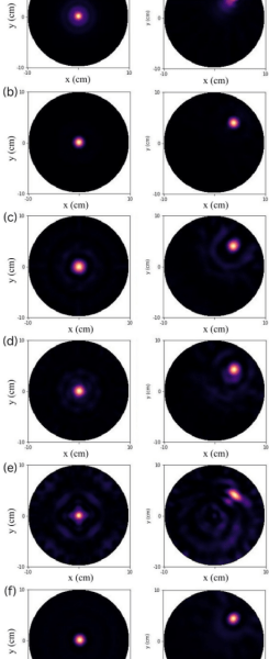
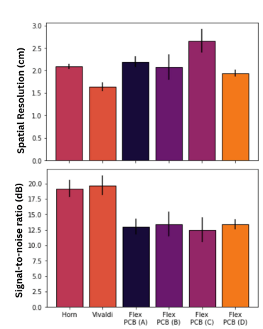
DAS images were reconstructed for the rod scans using each antenna type (Fig. 3). From these images, the spatial resolution and SNR were determined (Fig. 4). Overall, the Vivaldi antenna achieved the best spatial resolution and SNR, despite having lower gain than the horn antenna. Additionally, the Flex PCB (D) antenna demonstrated superior spatial resolution compared to the horn.
The rod images were also used to calculate the ideal SCR (Ta-ble 2). The results showed that the Vivaldi antenna exhibited the highest ideal SCR, followed by the horn antenna. Among the flexi-ble PCB antennas, Flex PCBs (A), (B), and (D) produced similar ideal SCR, while the largest Flex PCB (C) exhibited the lowest.
The SCR was recalculated using the breast phantom images (Table 2). As anticipated, the values were lower than the ideal case due to increased signal attenuation and clutter from the breast mim-icking material. Notably, the horn antenna performed worse than both the Vivaldi and Flex PCB (B) antennas, indicating that performance for a high-contrast point target does not directly translate to performance in a breast-mimicking geometry.
Table 2: Signal-to-clutter ratio determined using metal rods (ideal) and a breast phantom (realistic).
| Antenna | Ideal SCR (dB) | Realistic SCR (dB) |
|---|---|---|
| Horn | 20.3 ± 0.5 | 13.8 ± 0.9 |
| Vivaldi | 25 ± 1 | 18.8 ± 0.5 |
| Flex PCB (A) | 18.8 ± 0.7 | 13.7 ± 0.9 |
| Flex PCB (B) | 18.8 ± 0.9 | 15.0 ± 0.8 |
| Flex PCB (C) | 14 ± 1 | 12 ± 1 |
| Flex PCB (D) | 18.7 ± 0.7 | 10.6 ± 0.7 |
3.2. Intensity shift invariance
The metal rod images were used to evaluate the signal intensity as the rod moved off-axis. In an ideal case, a point-like target should yield a consistent reconstructed magnitude, regardless of location. However, due to the microwave propagation effects and antenna beam patterns, the intensity varied with radial position (Fig. 5). The maximum intensity difference was observed over a 5 cm radial distance (Table 3). Both the horn and Vivaldi antennas had decreasing intensities with increasing radial distance, whereas the flexible PCB antennas showed increasing trends with radial distance. The Flex PCB (D) antenna had the lowest variance, making it desirable for consistent contrast and sensitivity.
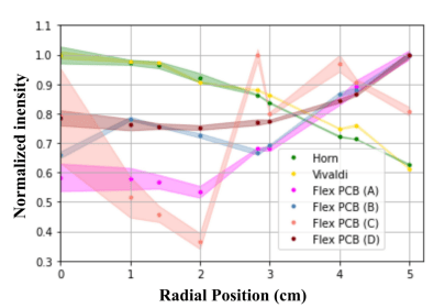
Table 3: Maximum signal intensity difference as the rod was shifted to varying polar coordinates within the imaging chamber.
| Antenna | Shift-invariance maximum intensity difference (%) |
|---|---|
| Horn | -37 ± 2 |
| Vivaldi | -38 ± 1 |
| Flex PCB (A) | 42 ± 3 |
| Flex PCB (B) | 35 ± 2 |
| Flex PCB (C) | 62 ± 7 |
| Flex PCB (D) | 21 ± 2 |
3.3. Contrast resolution
The contrast resolution was evaluated using the breast phantom DAS images with a tumour insert (Fig. 6) and fibroglandular insert (Fig. 7). The IVH curves were used to evaluate the contrast C% described by the horizontal spacing between curves. The aver-age C% was found for each scenario, and, as expected, contrast was generally higher for tumour responses than for fibroglandular responses.
The Vivaldi and Flex PCB (B) antennas achieved the highest contrast. Flex PCB (D) performed well in the metal rod experiments, but did not perform as well in the breast phantom experiments. The Flex PCB (C) antenna, the widest of the four PCB antennas, was significantly affected by clutter.
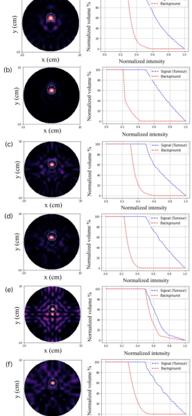
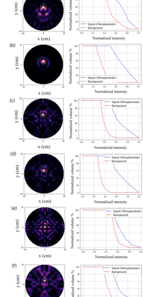
(e) Flex PCB C, and (f) Flex PCB D antenna.
Table 4: Average C% contrast for the tumour and fibroglandular signals.
| Antenna | Tumour signal contrast (%) |
Fibroglandular signal contrast (%) |
|---|---|---|
| Horn | 49 ± 4 | 27 ± 5 |
| Vivaldi | 63 ± 4 | 51 ± 1 |
| Flex PCB (A) | 45 ± 5 | 40 ± 4 |
| Flex PCB (B) | 59 ± 3 | 52 ± 4 |
| Flex PCB (C) | 9 ± 4 | 16 ± 6 |
| Flex PCB (D) | 48 ± 4 | 31 ± 2 |
4. Discussion
System hardware and design choices play a significant role in breast microwave sensing performance; however, the relative contribution of specific antenna characteristics remain incompletely understood. This work evaluates how antenna gain, beam pattern, and antenna size affect image quality while holding other system parameters constant.
In general, the Vivaldi antenna had the best spatial resolution, SNR, and SCR, despite having lower gain than the horn antenna. This indicates that gain alone does not determine image quality. When comparing flexible PCBs (A) and (B), which have similar physical sizes, the higher-gain antenna resulted in improved spatial resolution, SNR, and SCR. However, when comparing flexible PCBs (B), (C), and (D), which have similar gains, we observe that a smaller physical size improves the image quality.
The spatial resolution appears to be more strongly influenced by physical size, as the smallest UWB antenna, Flex PCB (D), achieved better spatial resolution than the horn antenna, despite its lower gain (6.4 dBi vs 12 dBi). The SNR appears to be influenced by both gain and beam pattern, as there is a noticeable difference in SNR between the horn and Vivaldi antennas and the UWB PCB antennas.
In the ideal metal-rod scenario, the horn and Vivaldi antennas have higher SCR than the UWB PCB antennas, indicating the benefit of higher directional sensitivity for a high-contrast target. How-ever, in a realistic scenario using breast-mimicking material, the horn antenna exhibited reduced performance, while the Flex PCB
(B) showed improved relative performance. This demonstrates that high-contrast point-target performance alone is insufficient for predicting image quality in a breast-mimicking environment.
Both the horn and the Flex PCB (C) have the largest azimuthal widths, which may contribute to their poorer performance in the realistic breast phantom. Additionally, the horn antenna has a reduced sensitivity to off-axis signals due to its narrow 3 dB beamwidth. These results suggest that image quality is influenced not only by antenna gain, but also by how effectively the antenna illuminates the imaging volume and couples to scattered fields.
As shown in Figure 5, omnidirectional antennas exhibit increasing intensity as signals move off-axis, whereas directional antennas are less sensitive to off-axis signals and exhibit decreasing intensity. In either case, the shift-invariance can negatively affect contrast and consistency. The Flex PCB (D) had the most favourable rod intensity variance, with only a 21% difference within a 5 cm radius.
Despite its high performance with the metal rods, the Flex PCB (D) was not the highest-performing UWB antenna in the breast phantom scans. This is likely due to its shorter height (5 cm), which does not fully encompass the length of the breast phantom (15 cm). This suggests that an ideal UWB aperture size may be achieved by minimizing the azimuthal width while ensuring the height is tall enough for the average breast.
Antenna gain and physical dimensions can significantly in-fluence image quality, however, the relative importance of these factors depends on the intended application. For large-scale clinical imaging systems, the Vivaldi antenna provides superior signal strength, spatial resolution, and image contrast. However, its rel-atively large size limits its suitability for portable imaging. In contrast, for low-cost and portable systems, PCB-based antennas offer a more favourable option due to its flexibility and compact size. Their imaging performance can be further optimized by bal-ancing key design parameters, including sufficient gain, a narrow azimuthal width, and adequate antenna height to cover the full length of the breast.
5. Limitations
While this study controls many system-level variables, the antenna parameters are not independently varied. As such, gain, beam pattern, physical dimensions, phase centre, and near-field effects remain partially coupled. Additionally, frequency-dependent antenna characteristics, including gain, beam pattern, and phase centre variation, are not explicitly accounted for in conventional DAS reconstruction algorithms. Consequently, the observed per-formance trends may differ when employing more sophisticated reconstruction techniques.
The cylindrical phantom used in this study represents a simplified breast model and evaluates the contrast between cancerous and fatty tissue. These phantoms provide a good estimation for attenuation and penetration depth expected in a real breast, however, detection abilities will become more difficult due to the complex anatomy and geometry. Additionally, the reconstruction techniques collapse three-dimensional phantoms into a two-dimensional im-age, which may affect accuracy when using geometry that varies along the length of the breast. Future work should incorporate frequency-dependent antenna characterization, multistatic mea-surements, and anatomically realistic phantoms to further evaluate the relationship between antenna design and BMS performance.
6. Conclusion
This study investigated the impact of antenna beam pattern, gain, and physical size on BMS image quality under controlled experimental conditions. Six antennas were evaluated, including a horn, a Vivaldi antenna, and four UWB PCB antennas. Measurements were conducted under identical system conditions to reduce the influence of differences in chamber, acquisition parameters, and reconstruction methods. The analysis included spatial resolution, signal-to-noise ratio (SNR), signal-to-clutter ratio (SCR), intensity shift invariance, and contrast resolution. Although higher gain can improve image quality, the Vivaldi antenna performed best overall despite having lower gain than the horn antenna. Furthermore, comparing the four UWB PCB antennas indicated that a smaller physical size (related to the aperture size) can improve resolution, reduce noise, reduce clutter, and enhance contrast, provided that the antenna height is sufficient to illuminate the full length of the breast. These findings highlight the importance of understanding antenna design tradeoffs when optimizing BMS systems, particularly for deployment in remote and low income regions.
- G. Fontaine, B. Loewen, S. Pistorius, “Impact of Antenna Design on Image Quality in Breast Microwave Radar,” in 2025 IEEE 20th International Symposium on Antenna Technology and Applied Electromagnetics (ANTEM), pp. 53–55, 2025. DOI: https://doi.org/10.1109/ANTEM64578.2025.11114101.
- C. Coleman, “Early Detection and Screening for Breast Cancer,” Seminars in Oncology Nursing, 33(2), pp. 141–155, 2017. DOI: https://doi.org/10.1016/j.soncn.2017.02.009.
- B. L. Niell, P. E. Freer, R. J. Weinfurtner, E. K. Arleo, J. S. Drukteinis, “Screening for Breast Cancer,” Radiologic Clinics of North America, 55(6), pp. 1145–1162, 2017. DOI: https://doi.org/10.1016/j.rcl.2017.06.004.
- B. Wagh, R. Chaluvarayaswamy, D. Pal, “Assessment of Adaptive Breast Cancer Screening Policies for Improved Mortality Reduction in Low to Middle Income Countries,” Asian Pacific Journal of Cancer Prevention: APJCP, 18, pp. 2375–2380, 2017. DOI: https://doi.org/10.22034/APJCP.2017.18.9.2375.
- B. Elias, E. V. Kliewer, M. Hall, A. A. Demers, D. Turner, P. Martens, S. P. Hong, L. Hart, C. Chartrand, G. Munro, “The burden of cancer risk in Canada’s indigenous population: a comparative study of known risks in a Canadian region,” International Journal of General Medicine, 4, pp. 699–702, 2011. DOI: https://doi.org/10.2147/IJGM.S24292.
- G. H. Rauscher, K. L. Allgood, S. Whitman, E. Conant, “Disparities in screening mammography services by race/ethnicity and health insurance,” Journal of Women’s Health (Larchmt), 21, pp. 154–160, 2012. DOI: https://doi.org/10.1089/jwh.2010.2415.
- R. A. da Costa Vieira, G. Biller, G. Uemura, C. A. Ruiz, M. P. Curado, “Breast cancer screening in developing countries,” Clinics (São Paulo, Brazil), 72, pp. 244–253, 2017. DOI: https://doi.org/10.6061/clinics/2017(04)09.
- US Preventive Services Task Force, “Screening for Breast Cancer: US Preventive Services Task Force Recommendation Statement,” JAMA, 331(22), pp. 1918–1930, 2024. DOI: https://doi.org/10.1001/jama.2024.5534.
- L. Wang, “Early diagnosis of breast cancer,” Sensors (Switzerland), 17, 1572, 2017. DOI: https://doi.org/10.3390/s17071572.
- K. S. Peairs, Y. Choi, R. W. Stewart, H. F. Sateia, “Screening for breast cancer,” Seminars in Oncology, 44, pp. 60–72, 2017. DOI: https://doi.org/10.1053/j.seminoncol.2017.02.004.
- A. Modiri, S. Goudreau, A. Rahimi, K. Kiasaleh, “Review of Breast Screening: Towards Clinical Realization of Microwave Imaging,” Medical Physics, 44, pp. 446–458, 2017. DOI: https://doi.org/10.1002/mp.12611.
- E. Porter, D. O’Loughlin, “Pathway to Demonstrating Clinical Efficacy of Microwave Breast Imaging: Qualitative and Quantitative Performance Assessment,” IEEE Journal of Electromagnetics, RF and Microwaves in Medicine and Biology, 6(4), pp. 439–448, 2022. DOI: https://doi.org/10.1109/JERM.2022.3218756.
- D. O’Loughlin, M. O’Halloran, B. M. Moloney, M. Glavin, E. Jones, M. A. Elahi, “Microwave Breast Imaging: Clinical Advances and Remaining Challenges,” IEEE Transactions on Biomedical Engineering, 65(11), pp. 2580–2590, 2018. DOI: https://doi.org/10.1109/TBME.2018.2809541.
- T. Reimer, S. Pistorius, “Review and Analysis of Tumour Detection and Image Quality Analysis in Experimental Breast Microwave Sensing,” Sensors (Basel, Switzerland), 23, 5123, 2023. DOI: https://doi.org/10.3390/s23115123.
- T. Reimer, F. Eashour, G. Fontaine, J. Krenkevich, S. Pistorius, “Evaluating System Design in Breast Microwave Sensing: Data and Image Quality in Multiple Systems,” in 2024 18th European Conference on Antennas and Propagation (EuCAP), pp. 1–5, 2024. DOI: https://doi.org/10.23919/EuCAP60739.2024.10500972.
- A-Info, “LB-20200-SF Broadband Horn Antenna 2–20 GHz,” 2026. https://www.ainfoinc.com/lb-20200-sf-broadband-horn-antenna-2-20-ghz-12db-gain-sma-female.
- Applied EM Innovations, “Ultra-Wideband Directional Antenna,” 2024. https://appliedem.wordpress.com/wp-content/uploads/2019/09/uwb700-d-datasheet.pdf.
- Taoglas, “Pylon, Wideband 5G Flexible PCB Antenna 600 MHz to 8 GHz,” 2026. https://www.taoglas.com/product/pylon-5g-flexible-pcb-antenna-600mhz-8ghz/.
- Siretta, “Echo 47 5G/4G Flexible Printed Circuit Wideband Antenna 600 to 6000 MHz,” 2026. https://www.siretta.com/products/antennas/echo-47/.
- Taoglas, “Maximus FXUB66 5G/4G Wideband 600 MHz to 8000 MHz Flexible Antenna,” 2026. https://www.taoglas.com/product/maximus-fxub66-ultra-wide-band-flex-antenna-ipex-mhf/.
- Siretta, “Echo 44 5G C-Band and Wi-Fi 7 Flexible Printed Circuit Antenna,” 2026. https://www.siretta.com/products/antennas/echo-44/.
- J. Krenkevich, G. Fontaine, E. Hluszok, T. Reimer, S. Pistorius, “Tissue Mimicking Materials for Shell-Based Phantoms in Breast Microwave Sensing,” IEEE Journal of Electromagnetics, RF and Microwaves in Medicine and Biology, 8(3), pp. 213–219, 2024. DOI: https://doi.org/10.1109/JERM.2024.3379747.
- S. Hagness, A. Taflove, J. Bridges, “Two-dimensional FDTD analysis of a pulsed microwave confocal system for breast cancer detection: fixed-focus and antenna-array sensors,” IEEE Transactions on Biomedical Engineering, 45(12), pp. 1470–1479, 1998. DOI: https://doi.org/10.1109/10.730440.
- T. Reimer, G. Fontaine, F. Eashour, J. Krenkevich, S. Pistorius, “Image quality analysis and comparison of three radar-based breast microwave sensing systems,” International Journal of Microwave and Wireless Technologies, 17(5), pp. 828–837, 2025. DOI: https://doi.org/10.1017/S1759078725000376.