Control and Monitoring Systems in Medium Voltage Distribution Networks in Poland – Current Status and Directions of Development
 , Lukasz Kajda, Marcin Tarasiuk, Tomasz Samotyjak, Zbigniew Stachowicz, Slawomir Kownacki
Adv. Sci. Technol. Eng. Syst. J. 6(6), 112–118 (2021);
 DOI: 10.25046/aj060615
The paper describes the control and monitoring systems installed in medium voltage networks by Polish distribution network operators. It also outlines the expected directions of development of these systems, specifies the functions of the individual system components and describes the requirements applicable to them. In particular, attention is paid to the implementation of functions to detect short-circuits and automatic voltage control on the low voltage side of the transformer using the on-load tap changer. It also describes the communication functions implemented by the control and monitoring systems and the methods of ensuring a guaranteed power supply for the above systems.
1. Introduction
Similarly, to the EU and other countries, the power network in Poland is split into a transmission network and a distribution network. In Poland, the transmission network consists of extra high voltage (EHV) lines with a rated voltage of 400 kV and 220 kV. The distribution network is made up of:
- high voltage (HV) lines with a rated voltage of 110 kV,
- medium voltage (MV) lines with rated voltage of 15-30 kV,
- low voltage (LV) lines with a rated voltage of 0.4 kV.
In Poland, there is one transmission system operator, whereas distribution networks are controlled and managed by five large distribution system operators (DSO) and several smaller local DSOs. Correct operation of the DSOs is supervised by the Energy Regulatory Office (ERO). This is a central governmental administration authority to regulate the fuel and energy market in Poland. The electricity market in Poland comprises more than 17.8 million consumers that consume approx. 175 TWh of electricity every year [1].
The condition of automation of MV networks in Poland has significantly improved in recent years due to the increase in the number of installed remote control and monitoring systems and as the extension and retrofit of SCADA systems. This is caused by the requirements to ensure the reliability of supply and keeping of the appropriate quality of electricity supplied. Currently, virtually all newly built substations installed within medium voltage distribution networks are equipped with telemechanics systems. A number of the existing substations are overhauled and equipped with telemechanics systems as well. These actions result from the DSO’s seeking the reduction of the time of restitution of consumer supply in case of failure, and thus the improvement of the area CTP (duration of the outage) and CP (frequency of the outage) indicators defined and required by the ERO. CTP is the area indicator for the interruption of electricity supply to consumers (the equivalent of SAIDI), whereas CP is the indicator for the frequency of interruptions of electricity supply to consumers in each area (the equivalent of SAIFI). The medium voltage distribution networks in Poland consist of overhead lines with a length of more than 225 thousand kilometres and cable lines with a total length of more than 85 thousand kilometres. In 2018, the number of medium voltage substations exceeded 265 thousand.[1].
The duration of interruptions in electricity supply to consumers is reduced by installing automation systems in MV networks within cable network substations and at load switches in overhead lines. These systems allow for remote control of switches and reconfiguration of MV networks so that at the moment of failure, the largest possible number of consumers can be supplied with electricity while shutting down the smallest possible fragment of the MV network. The requirements of the ERO towards the DSOs in the area of improvement of CTP and CP indicators in the coming years are included in the document [2].
2. Automation systems installed in the MV network
Telemechanics systems in medium voltage substations to which MV/LV transformers are connected are installed in parallel with devices that are elements of the Advanced Metering Infrastructure (AMI), such as balancing meters to measure energy on the low voltage side of MV/LV transformers. At certain DSOs, data concentrators are installed at the stations to enable communication with electricity meters installed at consumers and prosumers on the low voltage end, using the Power Line Communication (PLC) technique. Together with the telemetric control and monitoring systems, these devices use the communication system shared with the monitoring centres.
Along with the telemechanics systems, in medium voltage substation equipped with MV / LV transformers devices that are AMI (Advanced Metering Infrastructure) elements, such as balancing meters and data concentrators are installed.
Balancing meters measure energy on the low side of MV / LV transformers while data concentrators gather information from electricity meters installed at consumers and prosumers on low voltage, using the PLC (Power Line Communication) technique. For communication with the control centre, a common communication channel is used both by AMI and the telemechanics system.
The automation systems used for the control of MV overhead line load switches (as shown in Figure 1) and in MV cable network distribution substations (as shown in Figure 2) are made up of the below components:
- A telemetric control and monitoring system (telemechanics controller (RTU)) – allows for remote control and monitoring of load switches (LS) and MV circuit breakers (CB) equipped with an autonomous protection device (A.RELAY). The system collects and provides to the monitoring system (SCADA) binary signals (BI/BO) and additional information, e.g. concerning the status of fuses in the low voltage substation supplied from the MV/LV transformer (TR), and the operation of the guaranteed supply system and the condition of the overall facility (OVERALL) where it is installed.
- Fault detection systems (FD) – detect and indicate single-phase short circuits (ground faults) and phase-to-phase short circuits in the MV network. The system also allows for the measurement of voltage and current in the medium-voltage network. The fault detection systems may be independent devices or the fault detection function may be implemented in the telemechanics controller (as shown in the Figure 2). The current and voltage transformers or sensors (VT) (CT) are the source of measurement signals.
- Primary communication system (TETRA) based on the dedicated modem, connected with a controller using a serial link (COM) – provides communication with the dispatch centre.
- The backup communication system (GSM) ensures communication with the dispatching centre in case of failure of the primary communication system. It may be installed as a controller module (as shown in Figure 1) or as a separate GSM router (as shown in Figure 2) connected to the controller using the Ethernet link (ETH).
- Guaranteed power supply system (PS) with a 24 VDC battery (ACCU) – allows for the operation of the entire system in case of 230 V AC power supply voltage loss.
- At least one of the communication systems (primary, backup system) also functions as an engineering monitoring channel, which enables access to the configuration of some station devices (i.a. the telemechanics controller) through a WWW server or dedicated software.
- Except for the above, in a more extended version, the automation systems may contain the below additional systems (as shown in Figure 3):
- Advanced field terminals and protection devices (RELAY) that communicate with the controller using a serial link or Ethernet link and send statuses and measurements to the dispatcher system.
- Metering system for power quality parameters on the medium and low voltage sides.
- The balancing meter or AMI data concentrator with a balancing meter (AMI DC), that reads the indications of the subscriber energy meters and sends measurements to the settlement system (AMI).
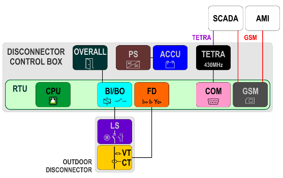 Figure 1: MV overhead switch control system
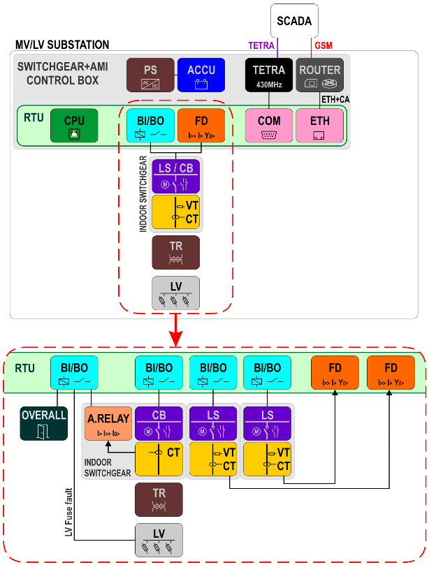 Figure 2: MV/LV substation control system
The automatic voltage control system (OTLC REG) – allowing for low voltage control through control of the on-load tap changer of the transformer (TR OTLC). This is one of the methods for limiting the voltage problems indicated above [3].
Some consumers are prosumers, e.g. have photovoltaic panels connected to the LV network through inverters (PV INV). The number of PV systems in Poland are increasing dynamically, that results in voltage problems, i.e. exceeded threshold voltage values in the LV network permitted under the regulations.
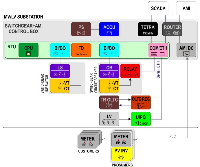 Figure 3: MV/LV station control system – extended option
3. Telemetric control and monitoring systems and systems for fault detection in the MV network
Failures in the medium voltage distribution network are the main reasons for the lack of energy supply to consumers [4], [5]. On average, 75% of the duration interruptions are associated with failures in the MV network, in particular with single-phase (earth) faults. The correct location of the fault within the network is of primary significance for the process of isolation of the damaged network section and restoration of the power supply in the remaining area.
The detection of earth faults based on current measurement only is sometimes ambiguous. The emergence of the low power voltage transformers (LPVT) and low power current transformers (LPCT) on the market allowed the application of conductance criteria (Y0, G0, B0) which required the voltage measurement additionally [6]. LPVTs installed directly in the separable connectors of MV switchgear act as the resistant or capacity voltage dividers. As for the LPCT the Rogowski coils are used most frequently. Due to the size and safety of use (low voltage on the secondary side), these devices are particularly suitable for use in MV switchgears installed within the network and in overhead line load switches.
Implementing within the MV network monitoring of current and voltage and reliable detection of short circuit current flow for earth faults and phase-to-phase faults enables quick detection of a damaged network section. Remote control of switches makes it possible to isolate the damaged network element and supply power, as far as possible, to other network sections within a timeframe of no more than 3 minutes. This duration was imposed by the Energy Regulatory Office in the requirements presented in [2], according to which power supply interruptions of up to 3 minutes are not included in the interruption duration indicator. It is not always possible to adhere to this time interval because the network operator has to have time to identify the existing situation, develop the switching strategy, assess the consequences of actions it wants to undertake, and carry out the sequence of switching operations.
The time needed for the performance of these actions may be reduced by implementing restitution automatics known as the Fault Detection, Isolation and Restitution (FDIR) [4], also referred to as the Self-Healing Grid (SHG) or Fault Location, Isolation and Service Restoration (FLISR). The task of the FDIR systems is to automatically analyze the network configuration [7] and perform the necessary switching operations within a timeframe of no more than 3 minutes.
The purposes of the FDIR are, i.e.:
- Reduction of the faulty network area.
- Reduction of the time of failure to supply electricity to consumers.
- Support for the organization of work of the fault-clearing services teams.
- Reduction of the interruption duration indicator and interruption occurrence frequency.
The FDIR is most often implemented in one of the three methods described below:
- Central automation system – the switches within the network are equipped with controllers with fault indicators. Information on the current network status (i.e. on the status of switches) and occurrence of faults is sent to a central system on an ongoing basis, where the sequence of switching operations to be carried out is developed to isolate the fault location and restore the power supply to the maximum number of consumers.
- Local automation system – within the MV network, circuit breakers (CB) are installed equipped with protection devices with different time delay settings, allowing for CB operation’s time selectivity in case of a fault circuit. Only the circuit breakers closest to the fault location are opened and the tie switch downstream the fault location is closed. More advanced mode of load switches operation is based on the exchange of the information related to the switch status between the controllers to develop and perform the switching sequence.
- Mixed automation system – uses both central and local automation system features. Its main advantage is the possibility to change the protection devices settings fitting them to the new network scheme, which was created after the switching operation. The new settings are calculated by the central system.
In Poland, the FDIR automation system implemented centrally, locally or in a mixed manner has been tested by the largest DSOs in pilot systems and is currently at the production deployment stage.
4. Automatic voltage control systems and measurement of electricity quality indicator
The installation of a large number of Distributed Energy Resources (DER), mainly PV, in the LV network, results in the DSO facing new challenges relating to compliance with the parameters of voltage supplying the consumers [8]. Even small power generating units connected directly to the low voltage network may result, in the case of low network load, in the increase in voltage above the permitted range. In turn, the decrease in LV at the MV/LV transformer output will fail to comply with the minimum voltage level when the DER sources do not operate.
One of the planned solutions implemented on a pilot basis to facilitate compliance with the permissible voltage levels in the LV network is the use of the transformer with an on-load tap changer [3].
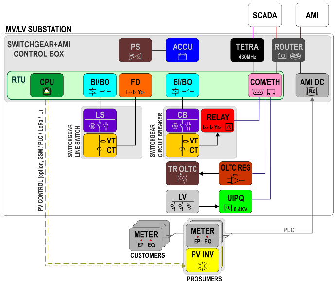 Figure 4: MV/LV station control system – voltage control in the LV network
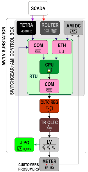 Figure 5: Algorithm for voltage control in the LV network
The algorithms for voltage maintenance in the permitted range are implemented in the telemechanics controller, which may source metering data from voltage measurements of the LV switchgear (as shown in Figure 4), measurements of electricity quality installed in LV outlet circuits and measurements from within the network obtained from the AMI system devices.
The telemechanics controller may also set the tap changer according to the command from the dispatcher system (as shown in Figure 5).
Other methods to maintain the voltage in the permitted range may comprise, e.g. the use of a symmetrizing transformer within the LV network to balance voltage in the particular phases [8] or remote control systems for DER sources, allowing for the limitation of the energy generated thereby, as described in more detail in [9]. Currently, the exceeded values of permitted voltage levels in the LV network result in the deactivation of PV microgeneration units as a result of activation of overvoltage protection devices in PV inverters, causing the reduction of prosumer profit and voltage oscillations in the network due to subsequent microgeneration activation and deactivation cycles. The extension of the telemechanics controller to include PV microgeneration unit control functions (control of reactive power consumption and reduction or disconnection of active power generation) will allow for the elimination of uncoordinated deactivation of PV microgeneration units and the related voltage oscillations.
In the locations with a large share of PV microgeneration units, the planned use of the metering systems for electricity quality indicators in the LV network, monitored by the telemechanics controller with communication with the SCADA system in the dispatcher centre, will allow for increasing the observability of the LV network and will provide data necessary for technical and economic analyses associated with the extension of LV networks.
5. Communication with dispatcher systems
The most common communication method used by the DSO involves the connection with the telemechanics controller through access using the cellular network purchased from an external provider. The communication may be effected through the modem installed in the telemechanics controller or through an external router with an appropriate modem. The solution including the external router is most often used when the same communication channel is also used by other systems installed in a substation. Another communication system often used by the DSO is the Terrestrial Trunked Radio (TETRA) system. This system is used for voice communication between the dispatchers and the personnel working in the field, but also enables the transmission of data, hence it is used in the control and monitoring systems of medium voltage networks of several DSOs in Poland. TETRA is not a generally available system. It is intended for public services and entities performing strategic tasks, such as the power sector. In particular, it is to provide reliable and safe communication when public networks are not available or overloaded (large-scale catastrophes or failures resulting in long-term loss of power supply for cellular network base stations).
In most of the substations located in cities or their vicinity, it is not necessary to install external GSM antennas. Usually, internal antennas are sufficient to establish a stable and efficient connection. The only exception is substations located in cellars of buildings several meters below the ground level. In such places, it is necessary to use antennas outside the building. External GSM antennas are also used in telemechanics systems of over-head line load switches which are often located outside urbanized areas.
The situation is different in the case of the TETRA infrastructure which uses lower frequency – approx. 450 MHz, which allows for the installation of base stations at greater distances. Due to the smaller number of base stations, in all facilities equipped with the TETRA infrastructure, antennas are installed outside buildings and, if possible, above the roofline (to ensure the “visibility” of the base station).
Irrespective of the communication system applied the communication with the dispatching systems always uses one of the protocols used in Poland: DNP 3.0 or IEC 60870-5-104.
It is expected that like the primary MV substations, in the future solutions for the secondary substations, the integrated telemechanics controller will be replaced with devices installed in the individual MV substation bays (as shown in Figure 6).
In each MV substation bay, autonomous devices will be installed for the implementation of all functions in this bay: remote and local control of the load switch or circuit breaker, handling the set of sensors for the measurement of voltage and current, detection of faults and faults and events recording.
The division of the telemechanics controller into several independent devices requires the use of an efficient and easy to implement communication system. The use of the standard described in IEC 61850 for the communication between the central controller and the field controllers is one of the solutions which attracts great interest. This standard uses the Ethernet interfaces that ensure high transmission speed and low delays in data transmission. It has been used for several years at high voltage and extra high voltage stations. At present, the second edition of the IEC 61850 standard is most often implemented in the devices, as numerous errors occurring in the first edition have been corrected and the number of modelled devices has been significantly extended.
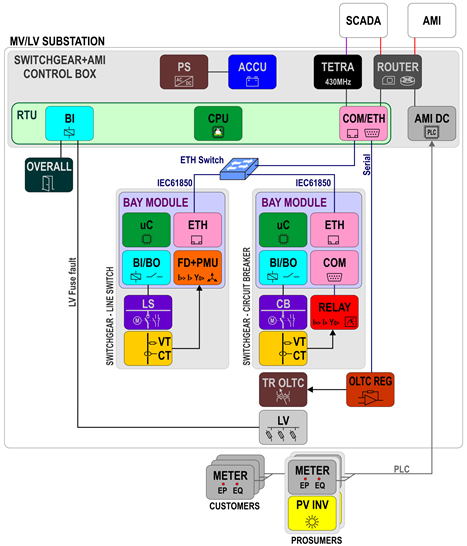 Figure 6: Distributed MV/LV station control system under IEC61850
The central controller located in the substation will be responsible for collecting general information (not associated with the individual medium voltage substation bays), e.g. information on the power supply system operation and door opening, and will function as a concentrator of data from field controllers and translator of protocols from IEC 61850 to DNP 3.0 or IEC60870-5-104. Currently, pilot projects for this type of system are carried out, one of them being a demonstrative system implemented in Poland within the EUniversal project, in which the authors of this paper are participating.
6. Security in communication systems
The power system is a critical infrastructure system, hence its protection against external threats is particularly important. One of the protection elements is the provision of ICT security to process (OT) systems, which comprise the dispatcher system along with the used remote transmission system and smart field devices that communicate with the dispatcher system [10].
The modern telemechanics systems implemented in Poland in the MV networks, as the OT system components, are equipped with mechanisms protecting against possible cyber attacks. The security mechanisms implemented in the telemechanics controllers enable the implementation of the OT system security policy adopted at a given DSO and ensure, i.a.:
- Mutual authentication and authorization of the communicating parties.
- Confidentiality and integrity of transmitted data.
Most of the Polish DSOs require the implementation of the above mechanisms to be compliant with the IEC 62351 standard commonly applied in the power sector. For the authentication and authorization, it is required to implement the support for the Public Key Infrastructure (certificates) (IEC 62351-9) in the telemechanics controllers, and to ensure data confidentiality and integrity, the support for the Transport Layer Security (TLS) protocol implementation is required in the presentation and transport layer (IEC 62351-3) of the communication architecture.
The authors of the paper envisage that in addition to the above-mentioned mechanisms, in the telemechanics controllers, additional functions relating to ICT security will be implemented to enable adjustment of controller configuration to the changing requirements of a given DSO, such as:
- Automation of certificate exchange, e.g. the use of the Simple Certification Enrollment Protocol (SCEP).
- Support for the Internet Protocol Security (IPSec) using certificates and for the Virtual Private Network (VPN).
- Support for the IEEE 802.1X standard – the function of a supplicant that initiates the request for authentication using certificates.
- Possibility of disabling not supported communication ports.
- Possibility of changing configuration concerning: addressing, TCP numbers, admissible master server addresses, etc.
- Update of internal software with source authorization and confirmation of new software integrity.
- Implementation of SNMP version 3.
At present, the DSOs, when preparing technical requirements for telemechanics controllers installed in the MV networks, demand the implementation of command authentication in the application layer following the IEC 62351-5 standard for network protocols such as DNP 3.0 over TCP and IEC 60870-5-104. For authentication and authorization purposes, the Public Key Infrastructure (PKI) certificate mechanism and TLS protocol are used. The protocol ensures a sufficient protection level for the communication that uses the TCP, due to which the requirement for additional authentication in the application layer seems redundant.
7. Guaranteed power supply systems
Concerning issues relating to the guaranteed power supply systems for the telemechanics systems installed in the MV network nodes, particular attention should be paid to the method of supply of secondary circuits of the MV switchgear and switch drives. This is usually a system comprising of a power supply unit with a battery charger and a battery bank. Most DSOs require that the battery capacity be adjusted to ensure the system operation for 24 hours after the power supply voltage loss. In the telemechanics systems installed in MV substations and load switches in overhead lines, batteries with a rated voltage of 24 V and capacity of several to 26 Ah are used. In the case of the majority of larger facilities with a greater number of feeders or equipped with additional devices, e.g. analyzers of network parameters or failsafe relays, larger capacity batteries are used.
In Poland, two solutions for guaranteed power supply systems that ensure sufficient inrush current and current of switch drive operation in the MV network are popular.
In the first solution, the telemechanics system is equipped with a power supply unit with a rated current lower than that required for the switch drive motors, and the backup power supply battery is at the same time a buffer for the power supply of the drive motors also when the primary 230 VAC voltage is present.
In the second solution, the telemechanics system is equipped with a power supply unit that enables current consumption sufficient for the supply of drives, and the battery is only a source of emergency power supply.
The first solution is cheaper and more popular and is suitable for the supply of drives and switchgears that do not consume energy when drives are at rest (switchgears without additional field instrumentation or overhead load switches). In this system, the telemechanics controller is connected to the main power supply unit (with battery charger) output and the drive is connected directly to the battery. When the primary power supply is in place, a temporarily increased current consumption from the battery by the drive motor does not significantly disturb the operation of the charging system of the power supply unit with a battery charger. In the case of primary power supply loss after the battery discharge, the power supply unit will disconnect the main output supplying the telemechanics controller, and the MV switchgear connected directly to the battery terminals will not cause its deep discharge, since it does not consume energy when the drives are not operating. The first solution becomes no longer functional when the MV switchgears are equipped with devices consuming current on a continued basis. These devices include field controllers, MV field protection devices, as well as power supply and control systems for drive operation. In such a situation, the second solution is used. At present, due to better availability and lower prices of power supply units with battery charger with a high input current, this solution is becoming increasingly popular.
A solution with supercapacitors is also implemented, as super-capacitors buffer energy to supply the drive, which according to the developers of this solution allows for maneuvering the switch when the batteries are worn out. The use of such a system is proposed mainly for overhead load switches.
8. Conclusions
The above described control and monitoring systems for switches in MV networks implemented in the form of centralized telemechanics controllers are typical systems used in recent years by Polish distribution network operators. However, in the nearest future, it is expected that the approach will change, and instead of centralized controllers, distributed telemechanics systems will be applied, which consist of field controllers placed in the particular MV switchgear feeders and a central controller. One of the possible communication solutions that may be used in MV substations is the connection of field controllers and the central controller using an Ethernet communication bus and the IEC 61850 communication standard, and GOOSE communication to send events.
Due to the current and planned dynamic development of PV micro-systems connected to the LV network in Poland and problems with the occurrence of exceeded voltage levels in the LV network, it is assumed that in section of the MV/LV transformer stations, it will be necessary to install automatic low voltage control systems, the various options of which are currently implemented and tested in pilot systems. The DSOs have not specified their requirements for such systems yet. The solution indicated in the paper, based on the use of the on-load tap changer, is one of the possible methods that may improve the parameters of the supply voltage in the LV network.
- H. Miko?ajuk, G. Parci?ski, J. Brasse, E. ?arek, D. Zaborska, I. Wro?ska, M. Zatorska, H. Bojanowska, E. St?pniak, Statystyka elektroenergetyki polskiej 2018, Agencja Rynku Energii S.A., Warszawa, 2019.
- Urz?d regulacji Energetyki, Regulacja jako?ciowa w latach 2018-2025 dla operatorów systemów dystrybucyjnych(którzy dokonali , z dniem 1 lipca 2007 r., rozdzielenia dzia?alno?ci), Urz?d regulacji Energetyki, Warszawa, 2018.
- C. Long, L.F. Ochoa, “Voltage control of PV-rich LV networks: OLTC-fitted transformer and capacitor banks,” IEEE Transactions on Power Systems, 31(5), 4016–4025, 2016, doi:10.1109/TPWRS.2015.2494627.
- A. Bab?, ?. Kajda, “Automatyka restytucyjna w sieciach ?rednich napi?? sposobem na popraw? jako?ci dostaw energii,” Wiadomo?ci Elektrotechniczne, 1(3), 36–41, 2017, doi:10.15199/74.2017.3.6.
- CEER, “CEER benchmarking report 5 .2 on the continuity of electricity supply data update,” Report on the Continuity of Electricity Supply, (February), 54, 2015.
- J. Lin?iks, D. Baranovskis, “Single phase earth fault location in the medium voltage distribution networks,” Scientific Journal of Riga Technical University. Power and Electrical Engineering, 25(25), 13–18, 2009, doi:10.2478/V10144-009-0002-6.
- A. Estebsari, E. Patti, L. Barbierato, “Fault detection ,isolation and restoration test platform based on smart grid architecture model using intenet-of-things approaches,” in Proceedings – 2018 IEEE International Conference on Environment and Electrical Engineering and 2018 IEEE Industrial and Commercial Power Systems Europe, EEEIC/I and CPS Europe 2018, Institute of Electrical and Electronics Engineers Inc., 2018, doi:10.1109/EEEIC.2018.8494449.
- M. Ozorowski, R. Ja?oza, “Poprawa parametrów jako?ciowych sieci zasilaj?cej nn z du?ym nasyceniem mikroinstalacji PV i stacji ?adowania EVC,” Wiadomo?ci Elektrotechniczne, R. 88, nr(5), 17–23, 2020, doi:10.15199/74.2020.5.3.
- M.M. Viyathukattuva Mohamed Ali, M. Babar, P.H. Nguyen, J.F.G. Cobben, “Overlaying control mechanism for solar PV inverters in the LV distribution network,” Electric Power Systems Research, 145, 264–274, 2017, doi:10.1016/J.EPSR.2016.12.002.
- J. ?widerski, P. Dopiera?a, M. ?winiarski, “Bezpiecze?stwo cybernetyczne transmisji danych pomi?dzy systemami nadrz?dnymi a telemetrycznymi sterownikami obiektowymi na potrzeby energetyki w ?wietle wymaga? normy IEC 62351,” Wiadomo?ci Elektrotechniczne, 1(6), 6–11, 2019, doi:10.15199/74.2019.6.1.