
Development of a Learning System for Robot Modular Manipulators


Adv. Sci. Technol. Eng. Syst. J. 11(5), 1–7 (2026);
 DOI: 10.25046/aj110501
This paper presents a modular robot learning system for robotics education, comprising a reconfigurable physical manipulator and an automatically configuring 3D simulation framework. Unlike prior modular manipulator systems that require manual software re-parameterization after hardware reconfiguration, the proposed system detects the assembled topology in real time through Dynamixel motor ID sequencing and renders a synchronized digital twin without any user intervention. The hardware platform uses three interchangeable joint modules—Twisting, Rotational, and Linear—connected via N42 neodymium magnets and an RS485 daisy-chain bus, enabling tool-free reconfiguration between SCARA (RRP) and Articulated (RRR) configurations in less than two minutes. Connector structural adequacy was validated experimentally: the measured axial magnetic moment capacity and perpendicular moment capacity both exceed the maximum robot-induced connector moment, and joint torques remain within the Dynamixel MX-28R 2.5 Nm specification under payload conditions. Protocol topology detection achieved 100% accuracy across all six tested assembly configurations. The simulation rendered at 60 FPS across five robot topologies—Cartesian, Cylindrical, Spherical, SCARA, and Articulated—providing a single platform for comparative study of serial manipulator architectures.
1. Introduction
Industrial robot manipulators are increasingly adopted in manufacturing worldwide. Thailand recorded a 36% growth in industrial robot installations, reaching 3,914 units in 2021 [1]. SCARA and Articulated robots dominate this market and are offered by all major vendors, including ABB, FANUC, Kawasaki, KUKA, Universal Robots, and Yaskawa. Accordingly, workforce training demand is rising sharply.
Training programs offered by institutions such as MARA (Manufacturing Automation and Robotics Academy) cover five topics across 30 brand-specific courses: (1) robot components and operation, (2) safety, (3) motion and coordinate systems, (4) programming, and (5) maintenance. Topics 1 and 3 contain universal content applicable regardless of robot brands specifically: joint types, link-joint-DOF relationships, coordinate frames, workspace, and jogging. However, courses are conducted on a single vendor's hardware, limiting trainees' ability to generalize these concepts across different joint configurations and robot architectures.
Existing modular robot platforms address hardware reconfigurability but do not couple it with an auto-configuring simulation. Systems such as those by [2, 3] require the user to manually update software parameters after changing the physical assembly. Consumer kits such as ClicBot [4] support diverse configurations but are not designed for industrial manipulator education. To the best of our knowledge, existing systems lack support for automatic, zero-configuration synchronization between digital twins and physically reconfigurable industrial manipulators.
2. Related Work
2.1. Modular Robot Systems
Modular robots have been studied extensively for locomotion and self-reconfiguration. M-TRAN III [5] demonstrated self-reconfigurable modules using active docking mechanisms but targeted locomotion rather than industrial-style serial manipulation. ClicBot [4] provided a consumer-grade reconfigurable robot kit with snap-fit connectors and a companion app for configuration management; however, its joint modules were not designed to replicate industrial arm kinematics (SCARA or Articulated), and configuration detection relied on a centralized app rather than embedded motor ID sequencing.
The Emerge robotics module [6] inspired the use of permanent magnets for inter-module connection, demonstrating that neodymium magnets could provide both physical attachment and electrical continuity. However, the Emerge system focused on stochastic self-assembly rather than manually reconfigurable serial manipulators.
2.2. Modular Manipulators
In [2], the author designed a manually reconfigurable modular manipulator with three revolute joints, using a clamp-based mechanical connector. A follow-up work [3] introduced a genderless coupling mechanism to simplify assembly. Both works demonstrated successful hardware reconfiguration but required a manual update of the robot kinematic model in software after each hardware change a limitation that the present system eliminates through automatic ID-based topology detection.
The ODIN robot [7] established the feasibility of RS485-based global bus communication for modular robots, and this architecture is adopted here. In [8], the authors proposed a modular architecture for industrial applications but did not address the problem of automatic configuration detection.
2.3. Comparative Summary
Table 1: Summary of the key characteristics of related modular robot systems relative to this work.
| System | Connector | Commu-nication | Manip. Config. | Auto-detect | Simulati-on |
|---|---|---|---|---|---|
| M-TRAN III [5] | Active docking | CAN | Locomotion | N/A | None |
| ClicBot [4] | Snap-fit | Proprietary | General | App-based | Mobile app |
| Hong et al. [2] | Clamp | RS485 | SCARA/ Articulated | No | None |
| ODIN [7] | Permanent magnet | RS485 | Locomotion | N/A | None |
| This work | Neodymium magnet + teeth | RS485 | SCARA/ Articulated | Yes (ID-based) | Auto-generating 3D (Processing) |
3. System Architecture
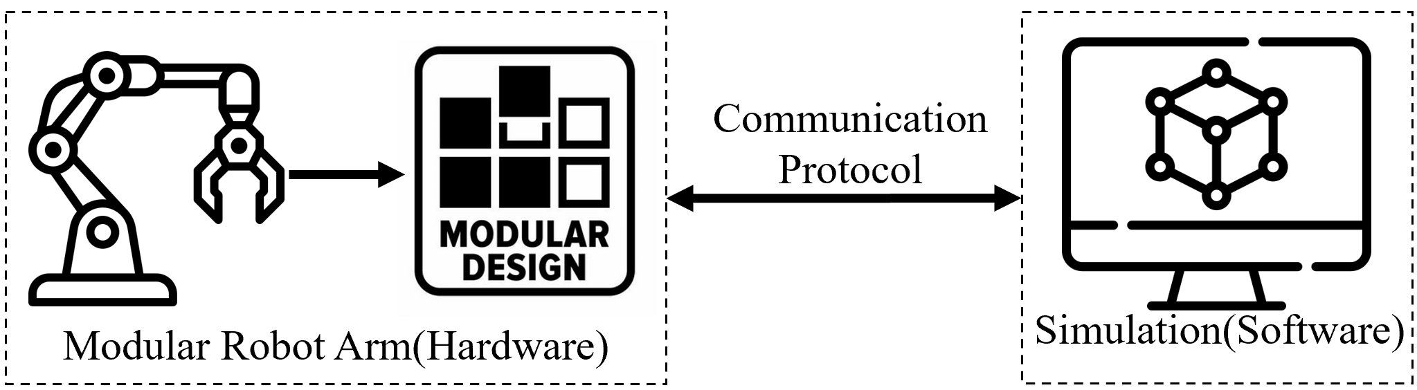
The learning system integrates three components: hardware joint modules, an electrical/RS485 communication bus, and a real-time 3D simulation. Figure 1 shows the overall architecture. The key design principle is that the simulation auto-generates the robot model from the ID list returned by the bus—no user configuration step exists between hardware assembly and simulation use.
4. Hardware Module Design
4.1. Configuration Analysis and Module Selection
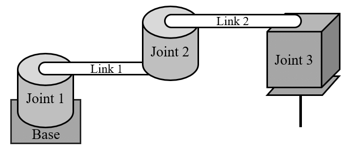
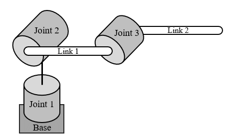
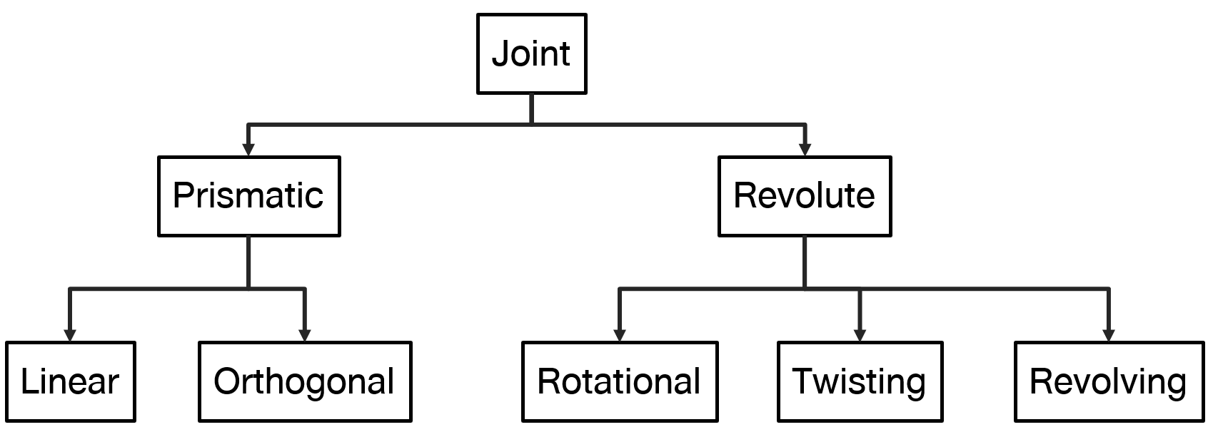
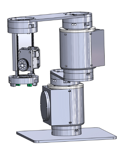
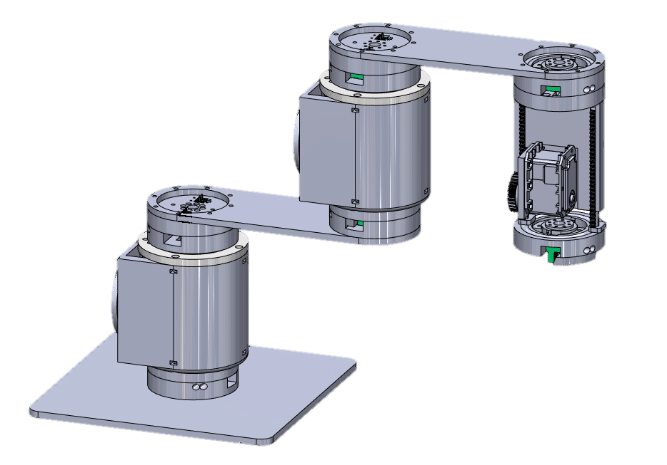
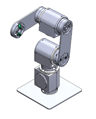
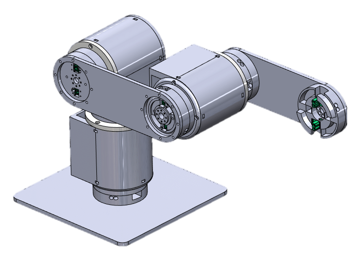
To determine the minimum module set covering both target configurations, the joint sequences of SCARA and Articulated robots are decomposed (Figure 2). A SCARA robot (RRP) requires: Base → Twisting Joint → Twisting Joint → Linear Joint. An Articulated robot (RRR) requires: Base → Twisting Joint → Rotational Joint → Twisting Joint. This analysis reveals that three motorized module types—Twisting, Rotational, and Linear—plus a passive Link module are sufficient for both configurations.
4.2. Module Specifications
All structural components are 3D-printed in PLA. Each motorized module uses a Dynamixel MX-28R servo (rated torque 2.5 Nm) with a fixed ID assignment that encodes module type—enabling automatic topology detection. Table 2 summarizes the specifications.
Table 2: Module specifications.
| Parameter | Linear | Rotational | Twisting | Link |
|---|---|---|---|---|
| Joint type | Prismatic | Revolute | – | |
| Range | 0–100 mm | 0–360° | 100/150 mm | |
| Weight | 200 g | 290 g | 100 g | |
| Actuator | MX-28R | – | ||
| Dynamixel ID | 4 | 2 | 1, 3 | – |
| Material | PLA | |||
| Communication | RS485 | Passive |
4.3. Assembled Configurations
Figure 4 shows the assembled SCARA and Articulated robots alongside CAD reference models. Assembly requires pressing module connector faces together; the magnets snap the faces into alignment and the interlocking teeth prevent rotation. Disassembly requires a deliberate lateral shearing motion, preventing accidental separation during operation.
5. Coupling Mechanism
5.1. Magnetic Connection
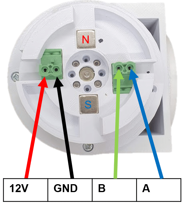
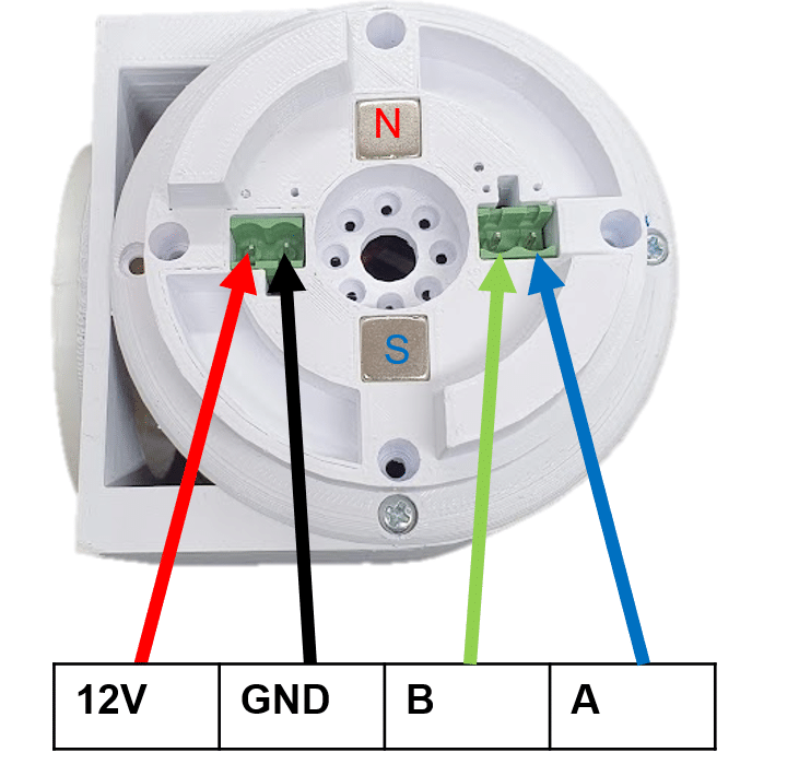
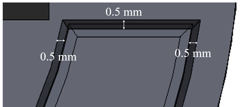
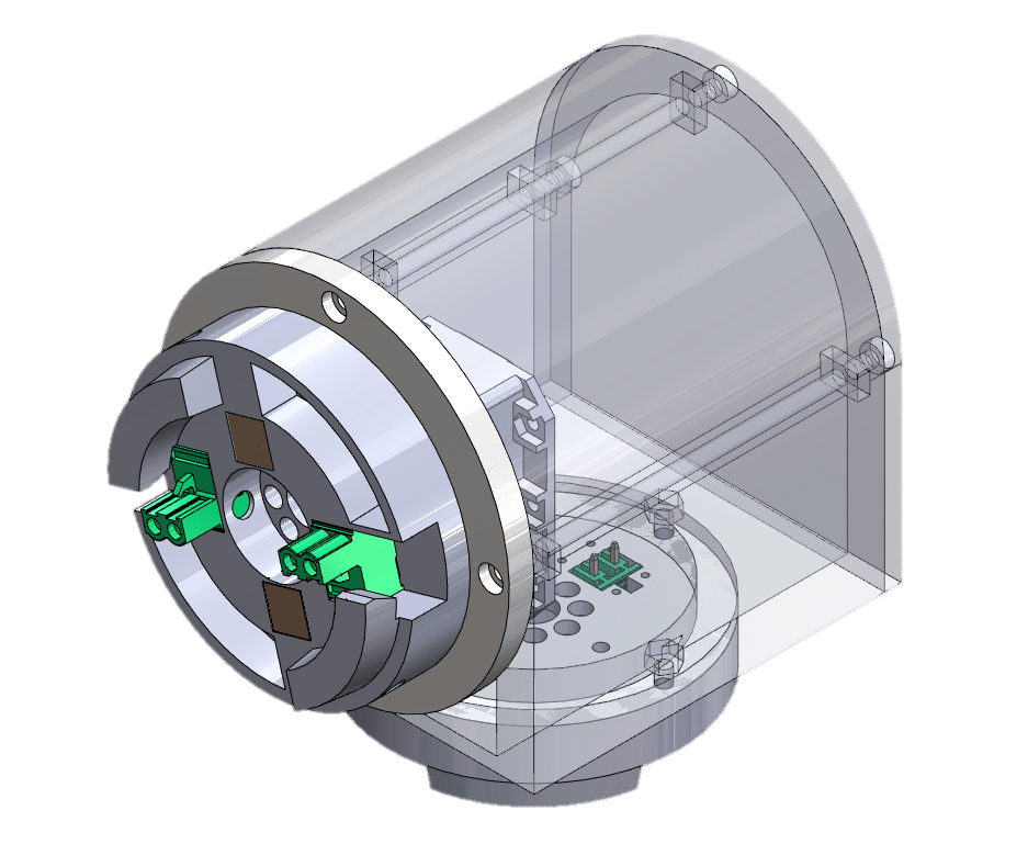
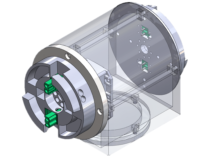
Inspired by the Emerge robotics module [6], N42 neodymium magnets (10×10×10 mm) are embedded flush in each connector face. A key characteristic of neodymium magnets is their extreme sensitivity to gap distance: a 1 mm separation reduces pull force from approximately 5 kg to 3 kg. The design therefore minimizes face clearance; a 0.5 mm intentional gap compensates for Ender 3 printer dimensional tolerances (typically ±0.2 mm) and ensures magnets reach near-contact after post-print fit. Two magnets per face are arranged in alternating N–S polarity, enforcing a unique mating orientation and preventing reversed electrical connections. Figure 5 demonstrates both connector faces.
5.2. Tapered Mechanical Teeth
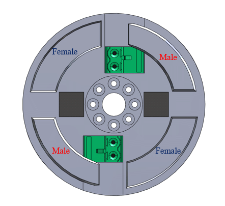
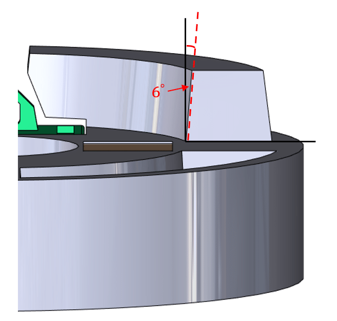
A teeth-and-slot profile resists rotational slippage between joined modules, with the design inspired by ClicBot's 2+2 male/female diagonal tooth pattern [4]. Male teeth are tapered at 6° to ease entry (Figure 6). Tooth dimensions: tip width 7.6 mm, root width 9.16 mm; socket width 10.16 mm. This provides 2.56 mm clearance at the tip and 1.0 mm at the root, accommodating print tolerances while maintaining shear resistance under operating loads.
5.3. Electrical Interface and Thrust Bearing
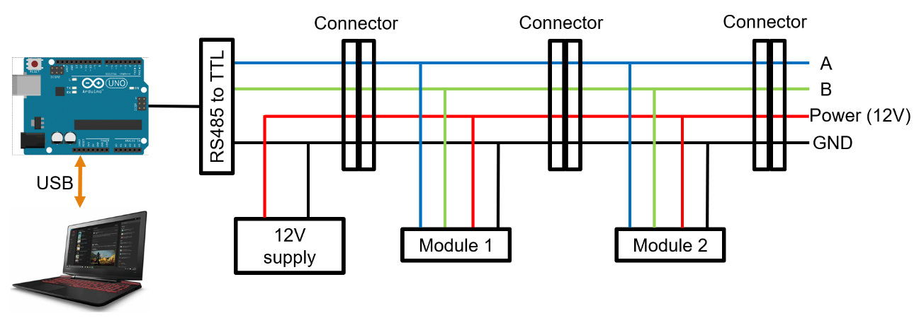
Four signals are routed through each connector—12 V power, GND, RS485-A, and RS485-B—using DEGSON pluggable terminal blocks (male on Output, female on Input). The alternating magnet polarity physically prevents reverse-polarity connection. An early prototype exhibited tilting because robot weight was transmitted directly to the Dynamixel motor shaft. This was resolved by integrating a custom thrust bearing race into the connector, transferring axial loads to the PLA housing and eliminating shaft bending.
6. Communication and Simulation System
6.1. Communication Protocol
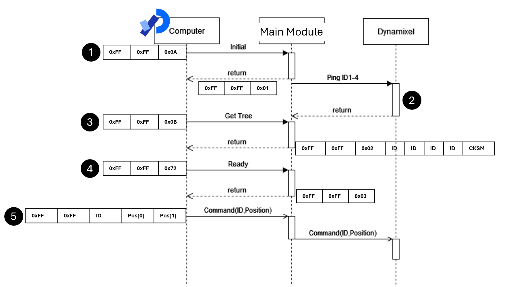
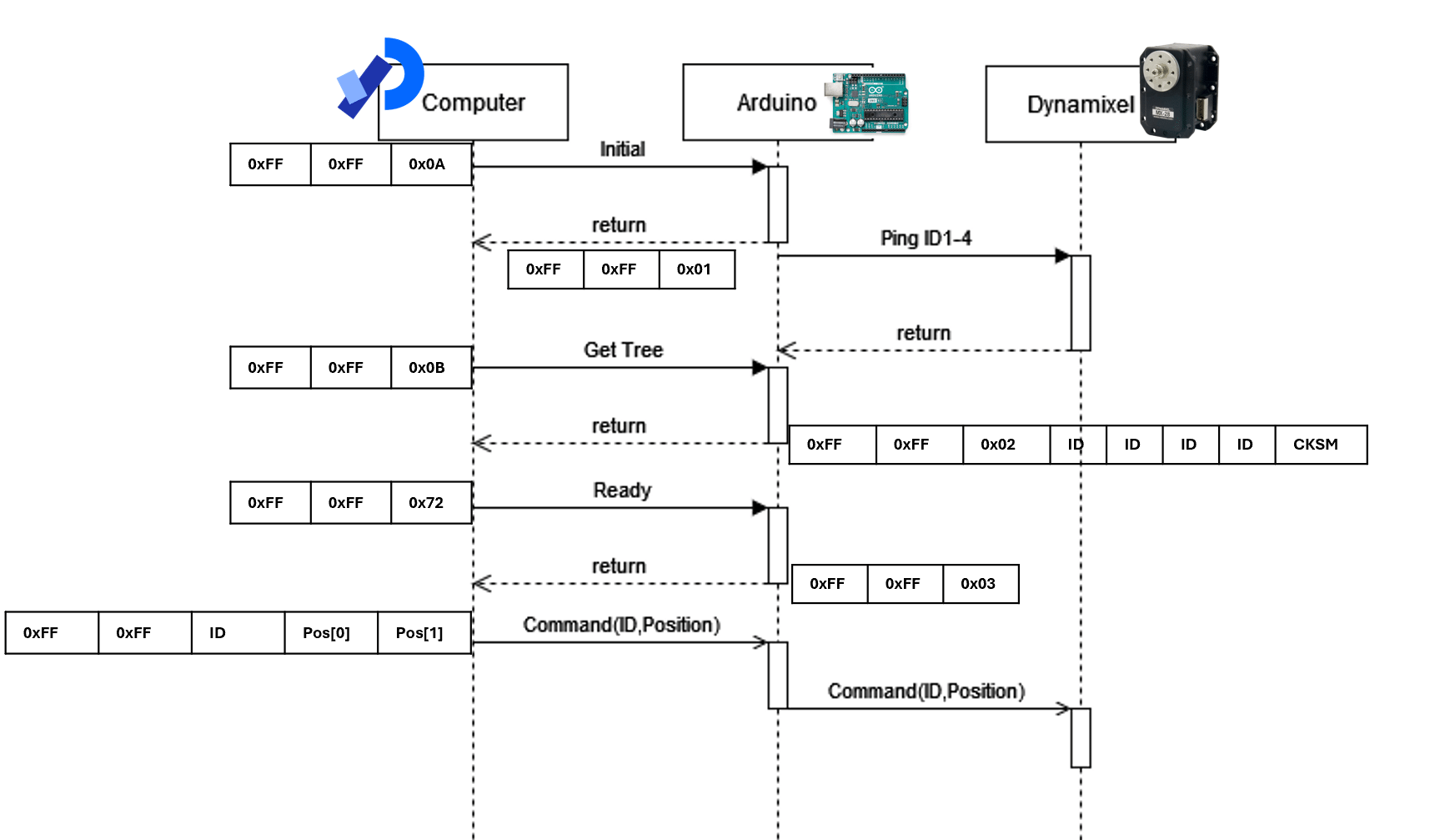
The PC (running Processing [9]) communicates with an Arduino Uno over USB serial; the Arduino drives the RS485 bus in half-duplex mode as network master, with Dynamixel motors as slaves. Five protocol steps govern each session:
- Check Arduino (0xFF 0xFF 0x0A): The PC polls the Arduino for its online status.
- ID Scan (0xFF 0xFF 0x01): Arduino pings Dynamixel IDs 1–4 in sequence; responds with a bitfield of present IDs.
- Get Topology (0xFF 0xFF 0x0B): PC requests assembly order. Arduino returns 0xFF 0xFF 0x02 [ID1] [ID2] [ID3] [ID4] [CKSM].
- Ready (0xFF 0xFF 0x72): PC sends ready signal; Arduino confirms with 0xFF 0xFF 0x03. Simulation auto-generates robot model from ID list.
- Motion Command: 0xFF 0xFF [ID] [Pos_Low] [Pos_High] — sent to physical robot and simulation simultaneously on each keypad input.
6.2. Topology Detection Logic
The ID-to-module-type mapping is fixed (Table 2): IDs 1 and 3 always correspond to Twisting joints, ID 2 to the Rotational joint, and ID 4 to the Linear joint. When the Arduino returns the ID sequence (e.g., [1, 2, 3] for Articulated; [1, 3, 4] for SCARA), the simulation maps each ID to its joint type and axis, instantiates the kinematic chain in order, and renders the 3D model. This design trades ID-reuse flexibility—the same ID cannot appear twice in one chain—for guaranteed, zero-ambiguity topology identification without any additional hardware (no topology sensors or RFID tags).
6.3. Simulation Framework
The simulation is implemented in Processing (v4) [9] for its built-in 3D pipeline, keyboard/mouse input, serial port access, and standalone executable export. Each joint segment is parameterized by: link length (integer, mm), joint rotation axis (x/y/z/−x/−y/−z in World Coordinate Frame), link extension axis, and joint type (0 = Prismatic, 1 = Revolute, 2 = Fixed). Forward kinematics are computed incrementally as joints are added. The display shows end-effector position (x, y, z in mm), individual joint angles or positions, and DOF count in real time. In Offline mode (no Arduino detected), the software generates a default 3-DOF Articulated robot for simulation-only use.
7. Engineering Analysis
7.1. Worst-Case Load Identification
Load analysis of the SCARA configuration shows that the base Twisting joint (Joint 1) experiences the maximum connector moment because it supports the combined cantilevered weight of two Links and two downstream joints. For the Articulated configuration, the Rotational joint experiences the highest combined static and dynamic torque. These two cases form the design basis for connector and actuator sizing.
7.2. Connector Moment (SCARA Base Joint)
The maximum bending moment M at the base connector is computed by summing gravitational contributions of all cantilevered masses at their respective moment arms from the connector pivot:
$$ M = \sum_i (m_i \cdot g \cdot L_i) $$
Substituting: two Twisting joints (290 g each), two Link modules (100 g each, 150 mm), at arms 0.04 m, 0.115 m, 0.190 m, 0.265 m:
$$ M_{\mathrm{robot}} = (0.1\times0.04 + 0.29\times0.115 + 0.1\times0.190 + 0.15\times0.265)\times9.81 = 0.636\ \mathrm{N\,m} $$
7.3. Actuator Torque (Articulated Rotational Joint)
The worst-case static and dynamic torque at the Rotational joint:
$$ \tau_{\mathrm{static}} = (0.29 + 0.1 + 0.1)\times9.81\times0.145 = 0.697\ \mathrm{N\,m} $$
$$ \tau_{\mathrm{dynamic}} = I\alpha = 0.0169\ \mathrm{kg\,m^2}\times10\ \mathrm{rad/s^2} = 0.169\ \mathrm{N\,m} $$
$$ \tau_{\mathrm{total}} = 0.866\ \mathrm{N\,m} < 2.5\ \mathrm{N\,m}\quad(\text{MX-28R rating}) $$
With a 150 g payload, \(\tau_{\mathrm{total}} = 1.104 + 0.314 = 1.418\ \mathrm{N\,m}\), which remains within the motor specification.
7.4. Connector Teeth Shear Analysis
The teeth resist the lateral shear component of gravity at the connector interface. For the SCARA base connector (total cantilevered mass m = 0.49 kg, tooth face angle θ = 84°, moment arm r = 0.05745 m):
$$ M_{\mathrm{teeth}} = (m g\sin84^\circ\cos84^\circ)r = (0.49)(9.81)(0.995)(0.105)(0.05745) = 0.029\ \mathrm{N\,m} $$
Since M_magnet (0.721–0.934 Nm) >> M_teeth (0.029 Nm), the magnetic force is the primary retention mechanism; the teeth serve exclusively as alignment guides and anti-rotation features.
8. Experimental Results
8.1. Magnetic Pull-Force Tests
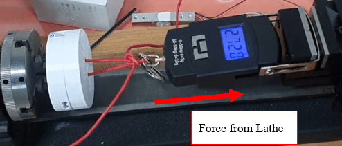
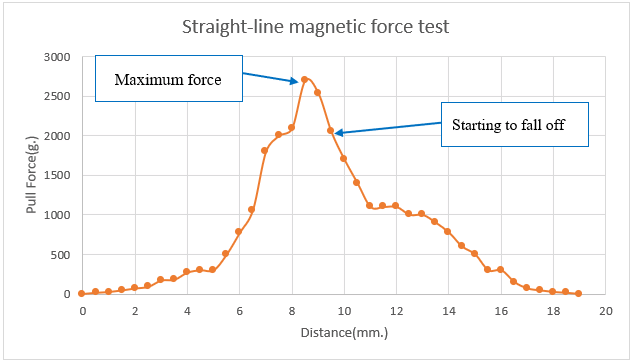
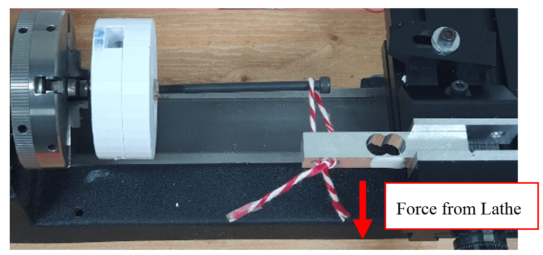
Two tests were performed using a precision lathe as a linear displacement fixture with a digital force gauge. Results are summarized in Table 3.
Table 3: Magnetic pull-force test results summary.
| Test | Max Force | Separation Force | Moment Capacity | vs. M_robot |
|---|---|---|---|---|
| Axial pull (face-to-face) | 2,720 g | 2,050 g @ 9.5 mm | 0.934 Nm | > 0.636 Nm ✓ |
| Moment pull (70 mm lever) | 1,050 g | 846 g @ 7.5 mm | 0.721 Nm | > 0.636 Nm ✓ |
The measured pull force is 73% lower than the datasheet value (10,080 g), which is attributable to 3D-printing dimensional tolerances creating a non-zero gap at the magnet interface. Despite this reduction, both moment capacity values exceed M_robot, confirming that the connector is structurally adequate for the designed robot.
8.2. Protocol and Topology Detection Accuracy
The protocol was tested across all six distinct assembly configurations achievable with the available module set (varying order and inclusion of modules). Table 4 reports the ID sequence returned by Arduino, the expected robot type, and whether the simulation generated the correct model.
Table 4: Topology detection accuracy across all tested assembly configurations.
| No. | Physical Assembly Order | ID Sequence Returned | Robot Type | Correct Model |
|---|---|---|---|---|
| 1 | Twisting–Rotational–Twisting | [1, 2, 3] | Articulated (RRR) | ✓ Yes |
| 2 | Twisting–Twisting–Linear | [1, 3, 4] | SCARA (RRP) | ✓ Yes |
| 3 | Twisting–Link–Rotational–Link–Twisting | [1, 2, 3] | Articulated (RRR) | ✓ Yes |
| 4 | Twisting–Link–Twisting–Link–Linear | [1, 3, 4] | SCARA (RRP) | ✓ Yes |
| 5 | Single Twisting joint only | [1] | 1-DOF Revolute | ✓ Yes |
| 6 | Twisting–Rotational–Twisting–Linear | [1, 2, 3, 4] | 4-DOF Hybrid | ✓ Yes |
Detection accuracy: 6/6 configurations (100%). Topology detection latency (from pressing 'r' to simulation model render) was measured at under 3 seconds across all configurations, dominated by the Arduino ID-ping loop rather than processing time.
8.3. Simulation Performance
The simulation rendered at a stable 60 FPS on the test hardware (Intel Core i7, 8 GB RAM). Physical-to-digital motion synchronization latency—measured from keypad input to visible motor movement and corresponding simulation update—was approximately 50–80 ms, determined primarily by the RS485 bus baud rate (57,600 bps) and Dynamixel packet round-trip time rather than Processing render overhead. The system rendered all five topologies (Cartesian PPP, Cylindrical PRP, Spherical RRP, SCARA RRP, Articulated RRR) without model changes, demonstrating the flexibility of the parameterized bone-arm approach.
9. Discussion
9.1. System Integration and Key Design Trade-offs
The central contribution—automated topology detection relies on the fixed ID-to-module-type mapping. This is a deliberate trade-off: it eliminates ambiguity (no two modules of different types share an ID) at the cost of preventing ID reuse within a single chain. Concretely, this means a chain cannot contain two Rotational joints or two Linear joints simultaneously. For the target educational use case (demonstrating SCARA and Articulated configurations), this is not a limitation; however, it does constrain the system's scalability to more complex configurations such as 6-DOF arms.
9.2. Scalability of the ID Scheme
The current ID assignment reserves IDs 1–4 for the three motorized module types. Scaling to N module types would require N reserved IDs on the same bus; the Dynamixel protocol supports IDs up to 253. The practical constraint is that a chain can contain at most one module for each reserved ID. A future extension could assign multiple non-conflicting IDs to the same module type (e.g., ID 1, 5 for Twisting) to allow repeated use; the simulation topology parser would need to group IDs by type range rather than by exact value. This extension does not require hardware changes.
9.3. Mechanical Connector Limitations
The 73% reduction in magnetic pull force relative to the N42 datasheet rating is the most significant hardware limitation. This arises from PLA printing tolerances (±0.2 mm on an Ender 3) preventing full-face magnet contact. Higher-precision manufacturing processes—SLA resin printing (±0.05 mm) or CNC-machined aluminum connectors—would substantially recover magnetic performance and improve the safety margin above M_robot. Thermal behavior of PLA under sustained load is also a concern: PLA begins to deform (creep) above approximately 60 °C, which may be reached at the motor housing under continuous operation. Future versions should evaluate PETG or ASA as structural materials.
9.4. Energy Efficiency and Maintenance Considerations
Energy efficiency. The platform is powered from a single 12 V supply distributed through the daisy-chain bus, and each motorized module contains one Dynamixel MX-28R actuator, so the SCARA and Articulated configurations each use three actuators. The moving mass is low (module masses of 100–290 g, Table 2), and the worst-case joint torque of 0.866 Nm (1.418 Nm with a 150 g payload) is well below the 2.5 Nm rated torque of the actuator, so the motors operate far from their torque limit. Commercial industrial manipulators are typically specified for much larger payloads and reach than are needed for teaching, and therefore use larger actuators and drives. The modular design also adds overhead: each connector adds housing mass and a small power loss in the pluggable terminals. Quantitative energy measurements were not recorded in this study. A direct per-task comparison with commercial arms therefore remains future work, in which the bus current will be logged over standard pick-and-place cycles.
Maintenance cost. Every module is a self-contained unit joined by tool-free magnetic connectors. A failed actuator or damaged housing can therefore be replaced individually, using the same procedure as reconfiguration (under two minutes, no tools), and the ID scan immediately reveals which module is missing or unresponsive. In contrast, conventional manipulators typically require trained technicians, vendor-specific tools, and recalibration after a joint is replaced, and the replaceable part is often a complete joint or arm assembly. In the proposed system the 3D-printed PLA parts can be reprinted at low cost, and the MX-28R actuator is the main recurring cost item. Two factors may increase maintenance effort: wear and creep of the PLA teeth and housings under repeated assembly and sustained load (see the discussion of mechanical limitations above), and the connector wear caused by frequent reconfiguration. A quantitative cost comparison depends on vendor pricing and service contracts and was not performed here.
9.5. Limitations and Future Work
Current limitations and planned improvements are:
- Fixed module inventory (1× Linear, 1× Rotational, 2× Twisting, 2× Link) limits configurations to SCARA and 3-DOF Articulated. Scaling to 6-DOF would require additional Rotational and Twisting modules.
- Hot-swap while powered is not supported due to RS485 bus contention during module insertion. A future bus arbitration scheme could enable this.
- The simulation does not yet support in-simulation robot programming (trajectory specification). This is the highest-priority planned extension.
- AR overlay integration (using the assembled robot's physical position to anchor a virtual coordinate frame display) is planned to enhance the educational value of the coordinate system module.
- Compatibility with external commercial robots (exporting the simulated joint sequence as a vendor-format program) is a future target.
- Energy consumption and maintenance cost were assessed only at the design level; measured current logs and a quantitative cost comparison with commercial manipulators are planned.
10. Conclusion
This paper presents the design, implementation, and experimental validation of a modular robot learning system. Three contributions are demonstrated. First, a magnetic quick-connect modular manipulator platform enables tool-free reconfiguration between SCARA and Articulated configurations in under two minutes. Second, a topology-aware simulation automatically detects the assembled robot configuration via Dynamixel ID sequencing—achieving 100% detection accuracy across six configurations with under 3 s latency—and renders a synchronized digital twin at 60 FPS without any manual re-parameterization. Third, connector mechanical adequacy is confirmed experimentally: axial magnetic moment capacity (0.934 Nm) and perpendicular moment capacity (0.721 Nm) both exceed the design requirement (0.636 Nm), and joint torques remain within the MX-28R specification under payload conditions (1.418 Nm). The system supports five serial manipulator topologies from a common module set, providing a single platform for comparative study of Cartesian, Cylindrical, Spherical, SCARA, and Articulated robot architectures.
Acknowledgements
The authors thank the Institute of Field Robotics (FIBO), King Mongkut's University of Technology Thonburi, for providing the laboratory facilities and equipment used in this work. The authors also thank the FIBO technical staff for their assistance with the mechanical fabrication and testing setup. A preliminary version of this work was presented at the 2023 Asia Conference on Artificial Intelligence, Machine Learning and Robotics (AIMLR 2023) [10]; the present manuscript extends that work with the coupling-mechanism engineering analysis, the magnetic pull-force and topology-detection experiments, and the expanded five-topology simulation results.
- International Federation of Robotics, Executive Summary: World Robotics 2022 Industrial Robots, International Federation of Robotics, Frankfurt, Germany, 2022.
- S. Hong, D. E. Choi, S. Kang, H. Lee, W. Lee, “Design of manually reconfigurable modular manipulator with three revolute joints and links,” 2016 IEEE International Conference on Robotics and Automation (ICRA), 5210–5215, 2016, DOI: 10.1109/ICRA.2016.7487728.
- S. Hong, W. Lee, K. Kim, H. Lee, S. Kang, “Connection mechanism capable of genderless coupling for modular manipulator system,” 2017 14th International Conference on Ubiquitous Robots and Ambient Intelligence (URAI), 185–189, 2017.
- Keyi Technology Co., Ltd., ClicBot, [Online]. Available: https://keyirobot.com/ (accessed November 2023).
- S. Murata, E. Yoshida, A. Kamimura, H. Kurokawa, K. Tomita, S. Kokaji, “M-TRAN: Self-reconfigurable modular robotic system,” IEEE/ASME Transactions on Mechatronics, 7(4), 431–441, 2002, DOI: 10.1109/TMECH.2002.806220.
- J. Neubert, A. P. Cantwell, S. Constantin, M. Kalontarov, D. Erickson, H. Lipson, “A robotic module for stochastic fluidic assembly of 3D self-reconfiguring structures,” 2010 IEEE International Conference on Robotics and Automation (ICRA), 2479–2484, 2010, DOI: 10.1109/ROBOT.2010.5509455.
- R. F. M. Garcia, A. Lyder, D. J. Christensen, K. Stoy, “Reusable electronics and adaptable communication as implemented in the ODIN modular robot,” 2009 IEEE International Conference on Robotics and Automation (ICRA), 1152–1158, 2009, DOI: 10.1109/ROBOT.2009.5152811.
- A. Faína, F. Orjales, D. Souto, F. Bellas, R. J. Duro, “Designing a modular robotic architecture for industrial applications,” 2013 IEEE 7th International Conference on Intelligent Data Acquisition and Advanced Computing Systems (IDAACS), 874–879, 2013, DOI: 10.1109/IDAACS.2013.6663052.
- B. Fry, C. Reas, Processing (Version 4), Processing Foundation, [Software]. Available: https://processing.org/ (accessed November 2023).
- P. Fuangpanichjaroen, N. Tirasuntarakul, O. Joochim, “Development of a learning simulation framework for modular robot manipulator,” 2023 Asia Conference on Artificial Intelligence, Machine Learning and Robotics (AIMLR), 1–5, 2023, DOI: 10.1145/3625343.3625353.