Walker Ergonomic Design for Visually Impaired Elderly

Adv. Sci. Technol. Eng. Syst. J. 4(3), 47–52 (2019);
 DOI: 10.25046/aj040307
The study proposed a self-driven guidance walker through user-oriented integration design. The common two-wheel drive performs left and right turn. By reducing the weight of the walker body, the durability of the battery can be increased. Secondly, we use a foldable structure so that the walker can be conveniently stored in a small space. A small number of sensors are required to reduce the complexity of signal processing. The front sensors of the walker are infra-red and ultra-sonic detectors, which determine and evade obstacles. The walker handle has three to five force sensors. The combination of the pressure data from these sensors can be used to determine the intent of the user, like turning or stopping.
1. Introduction
With the significant improvements in health science; the population of the senior citizens over 65 years old will be 15% by the year 2025 in Taiwan. Visually impaired persons often encounter difficulties in living an independent life. They need assistive devices to reduce visual obstacles.
Most of the seniors prefer to stay at home. When visually impaired people are unable to complete activities in their lives, they cannot participate in social activities. The assistance is vital for them to participate in ordinary life. Postmenopausal changes decrease the ability for visually impaired women to maintain postural stability [1]. Elderly blind persons had a slower walking speed, shorter stride length and longer time of gait [2].
In [3], the author addresses the motivation of elders to initiate exercise. The elderly are less active than the general population. Fear of injury is a common concern. Therefore, an exercise environment and regimen must be safe. Gradual exercise progression, increasing duration and frequency is significant. People should have the ability to exercise independently [4]. They should be able to maintain a sense of safety throughout the exercise.
1.1. Smart environment
Wireless technology evolved in recent years, designers can bring it to people with accessibility and ergonomic thinking. Many products found are based on a technology perspective and are less conceived from a user perspective. Article [5] suggests a way of deploying ubiquitous computing to cope with these difficulties. A friendly environment reveals itself by talking to the user with a ubiquitous module prototype.
Smart cane [6] offers voice and vibration alert. There is an antenna at the front of the guide stick to sense the RFID tag in the room. The guide wand transmits the signal to the blind person. Sometimes the contents of the tag cannot be read for a fast moving stick.
1.2. Active assistants
Active assistive walker usually has navigation ability. CMU developed robotic assistant in 2002 which lead the users to the destination. An active assistant gather environmental information, achieve obstacle avoidance with sensors. More sensors could increase the processing load and system cost.
An extended Kalman filter is applied to mobile robot navigation in a public environment which relies on geometric beacon [7]. Leonard et al. [8] used the geometric beacons for mapping and localization. The depth camera’s data provides indoor localization. Received signal strength (RSS) constructs the radio maps through different data sets and the environment’s coordinates [9].
Another study of Tsukiyama [10] proposed a monitoring system of solitary elderly based on urination, kitchen work, and physical cleanliness. The system monitors health status by using water flow sensors attached to faucets. Semi-autonomous control provided simple access through a handheld device. In case of problems, the robot contacts informal caregivers using teleoperation [11]. Another study [12] predicts the possible movement according to the output of the force sensor, the direction of motion conveyed by varying the center of mass elevation. A semi-passive walking robot designed using antagonistic actuation [13] with two pairs of legs, parallel links, and one torso. The robot could walk on horizontal surfaces while hung on the bar to prevent falling. The toe length is sensitive with lateral distance, and gait pattern of robot locomotion [14]. Gait function can be used as reference data in the control process. A passive exoskeleton developed with a clutch-spring mechanism and calf muscles. The engaging and disengaging timings were optimized through simulation for extending knee joint application [15].
The active assistants face the challenge of a trade-off between computing power and weight. The pursuit of the function increases the power consumption. Excessive functionality also makes the user unable to learn or unable to afford it. Heavy parts and large battery are also challenges for this to be implemented in living situations.
2. Concept design and prototyping
We proposed the concept design of an active walker with less weight [16, 17] to fulfill the need of the elderly. Smartphones have remote access and communication ability through the USB or Bluetooth connection.
2.1. Design process
Many of the previous designs focused on special features. From the user interviews, we found that such a model is large in size and complicated to construct, which makes it difficult to use. Complex functions also result in increased power consumption and battery drain. Here, conceptual design proposed from the perspective of human factors with an appropriate function, size, and weight.
Figure 1 shows the design process, and user reflection was collect with ergonomic consideration. The design process set a priority of design goal and tradeoffs of product concepts to confirm feasibly.
The digital model creates a prototype 3D printing which utilized in user evaluation. Electrical parts and interface module are placed with mechanical elements. An existing smartphone app has a built-in position sensor and voice notice. The measured data and user’s feedback results are collected to adjust the pressure sensing parameters to acquire better control.
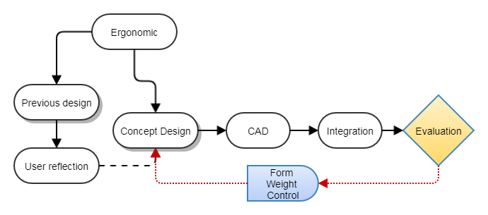 Figure 1: The design process of the people-oriented electromechanical integration design
As shown in figure 1, the ergonomic consideration ensures user’s requirements and functional integration. Evaluation test confirms the product features through a series of measurements.
2.2. Electrical components and sensors
The electronic parts and mechanical components are combined to achieve appropriate functions through system integration. The electrical components primarily follow sensing and control circuits.
The walker’s body has sensor units placed in front to determine and evade obstacles. The block diagram (Figure 2) shows the existing technologies such as motor controllers and sensors, which have widely been used in different fields. We proposed a link between pressure sensing and user intent.
2.3. Mechanical parts and chassis
The structural and mechanism components are configured with CAD system. The walker’s handle (Figure 2) has pressure monitor sensors. The handle sensors located corresponding to palm and finger contact areas. The pressure gathered from the distribution of charges with thin-film sensors. The pressure distribution helps to verify the current status of the user and adjust the walker’s speed (Figure 3).
The relationship between the visually impaired and the walker is like the way people lead them.
 Figure 2: Functional block diagram using a smartphone to control, some software builds in the mobile app. via the Bluetooth interface.
The user configures the parameters of the walker to fit an individual’s need. Typically, the handle has three to five sensors. The combination of the data from these sensors can determine the intent of the user (turning or stopping).
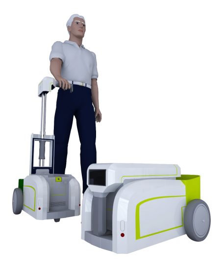 Figure 3: Perspective view of walker leads the visually impaired in the moving target.
3. Ergonomic design
The ergonomic design follows some rules; detail concerns: 1) the adjustable handle accommodates users of different heights within weight limit; 2) easy control and reduces the applied force; 3) fashionable style that is apart from handicap stereotypes.
3.1. Overall image
Primary purpose of the assisted walker is to take a walk with the visually impaired. Through the pre-set path and speed, the assisted walker allows the elderly to be involved in minor exercises in daily life, hence promoting a healthier lifestyle. The image of handicap is subjective to the acceptance of users. They are sensitive to negatively perceived in a social context. The form of the assisted walker is more aesthetically pleasing to customers, which may remove some of their mental pressures in purchasing and using the walker.
3.2. Weight and dimension
In [16] participants performed different lifting tasks, with three lifting heights. The working heart rate of the participants showed a significant difference during lifts. One of the design targets is to make it less heavy so that an individual can lift it comfortably. Put the user’s needs to the forefront, the weight of the walker was reduced to avoid injury and easy to carry. So we need to choose to remove unnecessary elements and function.
The weight of the car is 23Kg referring to the requirements of airline baggage which is a reasonable load for user. The parts are selected and configured under the premise of this weight limit.
3.3. Way of control
Safety is an important consideration for the elderly. To avoid the sudden rotation caused by the interference of walking, we set the stop button near the thumb. When the elderly consciously can’t follow or is too fast, they can manually stop the helper to prevent potential danger.
A user may choose the assistive mode and listen to the related information. Seniors face usability issues related to physical, mental, and cognitive impairments. Most of the elderly have limited experience with technology.
Observing the guidance for blind people is helpful for walker design. Usually, people follow the below steps to activate by a sighted person.
Offer an elbow and back up to the person’s outstretched hand. Walk at a comfortable pace by remaining a slightly behind.
Keep arms bent at a 90-degree angle. The visually impaired person will remain a half step behind as you begin walking.
Stop when you need to turn around and tell your follower. He or she will release your arm and wait until you offer it again.
Imagine that when we assist the elderly in crossing the road, we also support him or her on one side; so this is a more natural form of assistance. We choose one-handed operation; the prerequisite is that the elderly can still walk normally. It also avoids interference with the machine while holding both hands.
4. Evaluations
The measured pressure determines the user’s intention. The implement procedures are described in Figure 4.
4.1. Moldable clay
Moldable clay was used to demonstrate deformation during initial test. The handle was wrapped with clay evenly. The deformation of clay is related to the pressure distribution during usage.
User’s operations would be recorded in the change of shape to determine possible positions of sensors.
 Figure 4: The ergonomic study and implement procedures
 Figure 5: The side view of the pressure detector located on the handle (red dots are high-pressure area). The leading edge (Front or Ft.) is the direction of movement, and the trailing edge (Bk.) is the side of user.
There is less variation among the elderly in terms of palm-size. We choose the positions of sensors according to the magnitude of geometrical change (Figure 5).
When the old man is led forward, he may be towed and fall if the walker runs fast. If the walker turns quickly, the users also have challenges to follow. The sensors acquired the intent and conditions of the elder; so that the robot can adjust its speed.
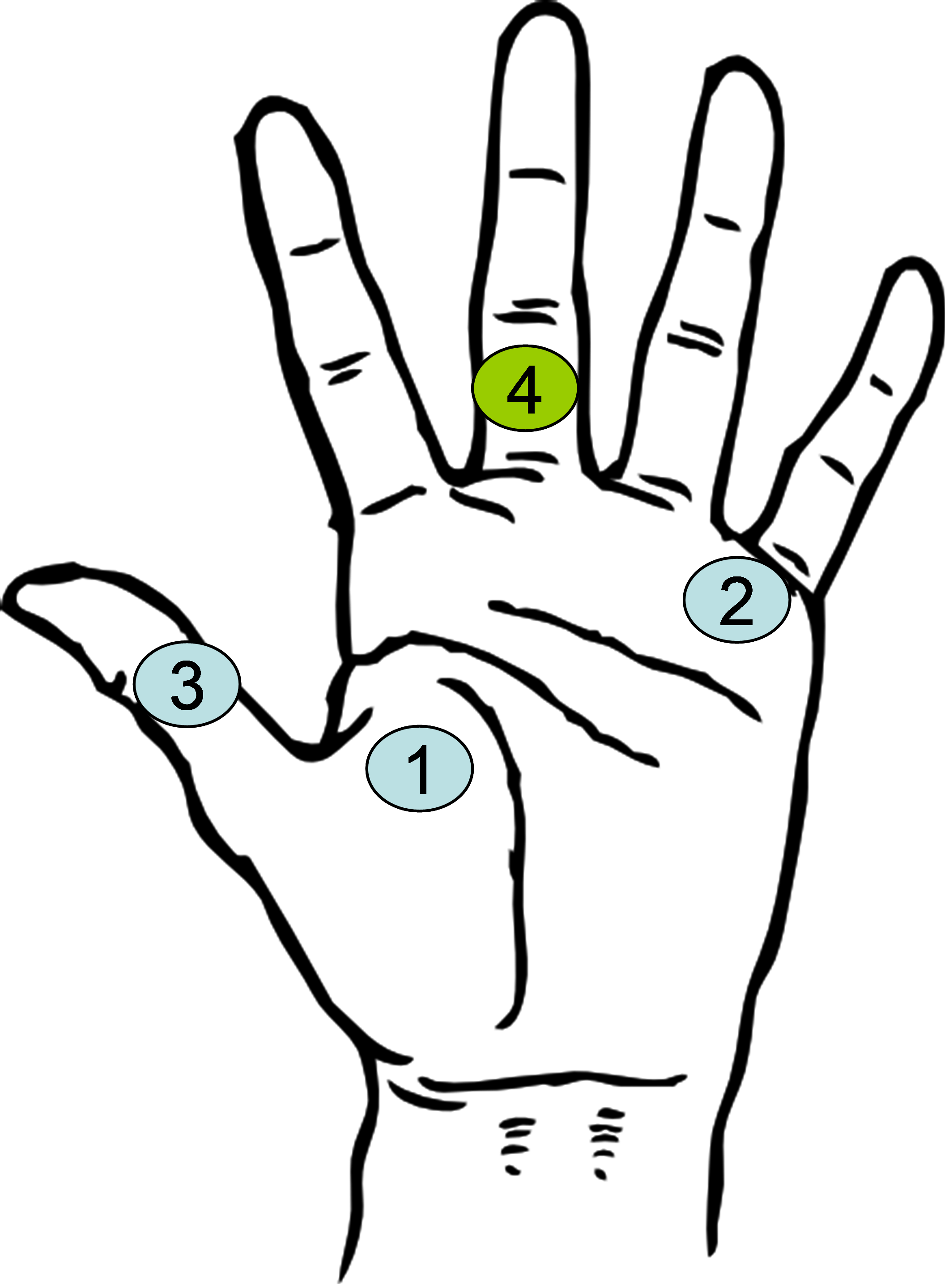 Figure 6: Sensor contact location
4.2. Pressure distribution
As shown in Figure 6, a user holds the handle during a walk. We adjusted the speed and direction of movement based on the pressure distribution. The purpose is to understand the appropriate location to detect the action intently. In this experiment, the driver did not have a built-in processor and measurement device, so an external sensor and wire is employed to transmit directly to the host PC for subsequent design.
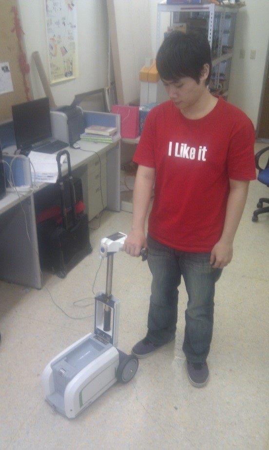 Figure 7: Measurement of pressure distribution.
We will start with five sensors and then re-evaluate that of fewer sensors (3 or 4) in a suitable position based on the pressure distribution observed from the clay.
Five sensors
We collect walking data of five sensors with five participants (Figure 7) to identify the pressure distribution. The measurements is based on the following situations.
- Condition 1:Right-hand control, go forward and intend to turn left,
- Condition 2:Right-hand control, go ahead and expect to turn right,
- Condition 3:Right-hand control, go forward and plan to stop.
The measured results are listed in Table 1-3.
Table 1: Pressure of left turn
| User | Thumb | Index | Middle | Ring | Little |
| A | Low | High | Medium | Low | Low |
| B | Medium | High | Low | Low | Low |
| C | Low | High | Low | Low | Low |
| D | Low | Low | Low | Low | Low |
| E | Low | Low | Low | Low | Low |
We find some variation in Table 1-3, such as:
- Table 1: the index finger of participant A.B.C is different from that of participant D and E.
- Table 2: the little finger pressure of participant E is different from that of others.
- Table 3: the index finger pressure of participant B is different from that of others.
Table 2: Pressure of right turn
| User | Thumb | Index | Middle | Ring | Little |
| A | High | Low | Low | Medium | High |
| B | Medium | Medium | Low | Low | High |
| C | High | Low | Low | Low | High |
| D | High | Low | Low | Low | High |
| E | High | Low | Low | Low | Low |
Table 3: Pressure of sudden stop
| User | Thumb | Index | Middle | Ring | Little |
| A | Low | Medium | Medium | Medium | Medium |
| B | High | Low | Low | Low | Low |
| C | Low | High | High | High | High |
| D | Low | High | High | High | High |
| E | Low | High | High | High | High |
Discussion
Depending on the size of the participant’s hand, some users apply pressures by the palm, which made the finger pressure to be less apparent. This variation causes a limitation of using pressure data to determine the user’s intent.
The way to overcome this difference is to reduce the unnecessary sensors and to tailor the handle’s shape according to the size of the user’s hand. Just as people buy a shoe with a specific size, the handle’s shape needs to fit the user’s hand.
The personal handle can be printed in a 3D facility at a reasonable cost — the specific handle shape made according to the clay model, and adjusted 3D model by reverse engineering. Afterwards, the sensors are then placed in the correct position of the handle.
Three / four sensors
The price of the sensor is high, so we hope to know the possible placement position with a limited number of sensors. Three and four sets of sensors placed to record the user’s main motion intent sequentially. The user holds the handle and records the pressure at each position. Based on observations, we infer the position of the sensor that is suitable for the user.
The measurement of three/four sets of sensor placement summarized in (Figure 8, 9). The position for the three sets of sensors for different users is not exactly the same, which is due to the difference in the size of the palm and personal holding habits.
According to the three intentions we want to distinguish (scenario: left turn, right turn, and stop), the test results of the three sensors (Figure 8). We found that the three values at sensor 1 are identical; there is a significant difference in sensor 2; the right turn is similar to the stop at sensor 3. Although the sensor 2 is able to resolve the three intents, in order to improve the reliability of the results, we continue to try four sensors.
 Figure 8: Pressure test results when using three sensors. The three lines represent the values of the pressures presented at each sensor when three actions are performed (left turn, right turn, and stop). The pressure sensing distribution is different when performing three actions.
The fourth pressure sensor was added to the first section of the finger joint (the leading edge of the walking handle). As shown in Figure 9, the test results of the four sensors are shown in the figure. We found that the three values of intent at sensor 1 are identical; there is a notable difference at sensor 2; the right turn is still similar to the stop at sensor 3; there is a significant difference at sensor 4. The sensor 2 and 4 are able to verify the three intents reliably.
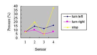 Figure 9: Pressure test results when using four sensors. The three lines represent the values of the pressures presented at the four sensors when performing three actions (left turn, right turn, and stop). The difference in pressure sensing distribution is more obvious when performing three kinds of actions.
4.3. Pressure variation with time
Thin-film sensor applied to acquisition the pressure variation with time — f sensors placed on the different contact area.
The sensor is 0.208mm thick and 14mm in width and sensing diameter is 9.53 mm (Figure 10). The sampling rate is 20 Hz and the data is fetched through the serial port.
The measured pressure is plotted in Figure 11; the maximum force occurs in two situations: while turning, or when the walker hits an object. The maximum value does not last long (0.3-0.4 sec.). The result of the fourth sensor near the middle finger is shown in Figure 11(a), it can be found that in the temporary stop operation situation, the value of the fourth sensing zones becomes significantly more extensive, and scenarios can be separated. The measured data show that the ‘stop’ scenario, the sensor provide good variation to distinguish it at 10.6 sec. Figure 11(b) has a gently varying waveform showing a continuous force-applying state, and a glitch shows a collision.
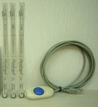 Figure 10: Thin-film sensor and configurations
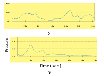 Figure 11: Sensor’s responses: (a) the second sensor during turns left, (b) the fourth sensor during the collision and stop.
We divide the value of the sensor into three different levels; low-level (< 5%), high-level (>14%), the median level in between. If the signal maintained at the same level for a certain period, the phenomenon presented a user’s action. The maximum pressure value maintained for 0.3 sec during turning moment (Figure 11.a).
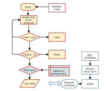 Figure 12: Flow chart of the Arduino sensing module
4.4. Implementation
The sensing module of the walker can implement with Arduino, which connects the four pressure sensors to the analog input pins of A0 to A3 (digital value 0-1023). The percentage of the Y-axis on the left side of Figure 11(b) represents the maximum measured value of the pressure sensor. We set a high pressure zone is above 14% (digital value 143), and a low pressure zone is below 5% (digital value 51), and a medium zone between the two (range 5%-14%). For example, in 2sec time (sampling rate is 20 Hz), the high pressure value is in the range of 0.75 seconds to 1.3 seconds, 1.75 seconds to 2.0 seconds; the low pressure time is between 0.1 seconds and 0.45 seconds, and the rest is medium pressure value. When maintaining the same level for a period of time, we can compare the pressure distribution of the four pressure sensors to predict the user’s intention. The sensing module determines the rotation or deceleration through a logic judgment and controls the rotation speed of the motor through the voltage value of the output pin (Figure 12). There are many applications on the phone that handle positioning and navigation. The sensing module can also be connected to the mobile phone via Bluetooth, and the action to be performed is notified to the elderly by the voice of the mobile phone without being overwhelmed.
5. Conclusions
The walker is suitable for elderly in public environments, such as hospitals or retirement homes. The concept design emphasized on ergonomic features; such as weight reduction, folding, sensing the user’s intent, and the like. Physical prototype and hardware circuit implementation is ready-to-expand Arduino module to perform force sensing. The smart phone app helps the elderly to move in a safe environment.
Conflict of Interest
The authors declare no conflict of interest.
Acknowledgment
This research was supported by the National Science Council, Taiwan, ROC, under grant NSC 99-2221-E-324-026-MY2. We gratefully thank Wenjie Xiao and Yusheng Huang for model making and the field test.
- Z. Maćkowiak, W. Osiński, and A. Salamon, “The effect of sensorimotor training on the postural stability of visually impaired women over 50 years of age,” Journal of Women & Aging, 27(1), 68-80, 2015. https://doi: 10.1080/08952841.2014.928140
- T. Nakamura, “Quantitative analysis of gait in the visually impaired, disability and rehabilitation” (19)5, 194-197, 1977. https://doi: 10.3109/09638289709166526
- E. M. Phillips, J. C. Schneider, and G. R. Mercer, “Motivating elders to initiate and maintain ex-ercise1” Archives of Physical Medicine and Rehabilitation, (85)1, 52-57, 2004.
- K. Rector, “Exploring the opportunities and challenges with exercise technologies for people who are blind or low-vision” in 2015 17th International ACM SIGACCESS Conference on Computers & Accessibility, Lisbon, Portugal, 2015.
- C. Vlad, F. Röthenbacher, “The Chatty Environment–providing everyday independence to the visually impaired” in Workshop on Ubiquitous Computing for Pervasive Healthcare Applications, UbiComp, Seattle, Washington, USA, 2003.
- M. H. A. Wahab, A. A. Talib, H. A. Kadir, A. Noraziah, A. A. Mutalib, “Smart cane: Assistive cane for visually-impaired people” arXiv preprint, 1110-1115, 2011.
- Sorour S, Lostanlen Y, Valaee S, Majeed K., “Joint indoor localization and radio map construction with limited deployment load,” IEEE Transactions on Mobile Computing, (14) 5, 1031-43, 2015.
- J. J. Leonard, H. F. Durrant-Whyte, “Mobile robot localization by tracking geometric beacons” IEEE Transactions on Robotics and Automation, (7)3, 376-382, 1991.
- J. Biswas, M. Veloso, “Depth camera based indoor mobile robot localization and navigation” in 2012 IEEE International Conference Robotics and Automation (ICRA), St. Paul, MN, USA, 2012.
- T. Tsukiyama, “In-home health monitoring system for solitary elderly” Procedia Computer Science, (63)1, 229-35, 2015.
- Mast, M., Burmester, M., Graf, B., Weisshardt, F., Arbeiter, G., Španěl, M., & Kronreif, G., “Design of the human-robot interaction for a semi-autonomous service robot to assist elderly people,” in Ambient Assisted Living, 15-29, Springer, Cham, 2015.
- Granados, Diego Felipe Paez, et al., “Guiding human motions in physical human-robot interaction through COM motion control of a dance teaching robot,” Humanoid Robots (Humanoids), presented at the 2016 IEEE-RAS 16th International Conference, Cancun, Mexico, 2016.
- T. Yano, J. H. Lee, and S. Okamoto, “Development of a biped walking robot with antagonistic actuation” International Journal of Mechanical Engineering and Robotics Research, (5)3, 196-201, 2016. https://doi: 10.18178/ijmerr.5.3.196-201
- V.-T. Nguyen and H. Hasegawa, “Effect of toe length on biped walking behavior,” International Journal of Mechanical Engineering and Robotics Research, (7)6, 599-603, 2018. https://doi: 10.18178/ijmerr.7.6.599-603
- Z. Shen, S. Sam, G. Allison, and L. Cui, “A simulation-based study on a clutch-spring mechanism reducing human walking metabolic cost” International Journal of Mechanical Engineering and Robotics Research, (7) 1, 55-60, 2018. https://doi: 10.18178/ijmerr.7.1.55-60
- A.S. Abadi, A. Mazlomi, A.H. Jafari, “Effects of box size, frequency of lifting, and height of lift on maximum acceptable weight of lift and heart rate for male university students in Iran” Elvectronic Physician, (7)6, 1365-1370, 2015.
- S. Azenkot, C. Feng, and M. Cakmak, “Enabling building service robots to guide blind people: A participatory design approach,” in the Eleventh ACM/IEEE International Conference on Human-Robot Interaction, Christchurch, New Zealand, 2016. https://doi: 10.1109/HRI.2016.7451727